Polished rod rotator

a rotator and rod rotator technology, applied in machines/engines, positive displacement liquid engines, boreholes/well accessories, etc., can solve the problems of accelerating the wear of sealing packers, reducing so as to achieve the effect of increasing the wear resistance of wearing equipment and high rotation angl

Inactive Publication Date: 2010-12-28
ALI ZADA VAGIF +1
View PDF5 Cites 26 Cited by
  • Summary
  • Abstract
  • Description
  • Claims
  • Application Information

AI Technical Summary

Problems solved by technology

This method of using rod rotators in pumping equipment is less effective for several reasons.
Consequently, this situation results in the accelerated wear of sealing packers of wellhead stuffing box that seal the head of the well and thus, necessitate frequent replacement of sealing packers.
Namely,1. They can achieve the objective of preventing unwanted unscrewing of string of sucker rods2. They do not achieve the objective of increasing wear resistance of wearing equipment3. They do not achieve the objective of decreasing the deposits of wax and paraffin on the walls of tubing and sucker rods.
This fact explains the inevitable increase in tubing rotators' mass.

Method used


Image

  • Polished rod rotator
  • Polished rod rotator
  • Polished rod rotator

Examples


Embodiment Construction

)

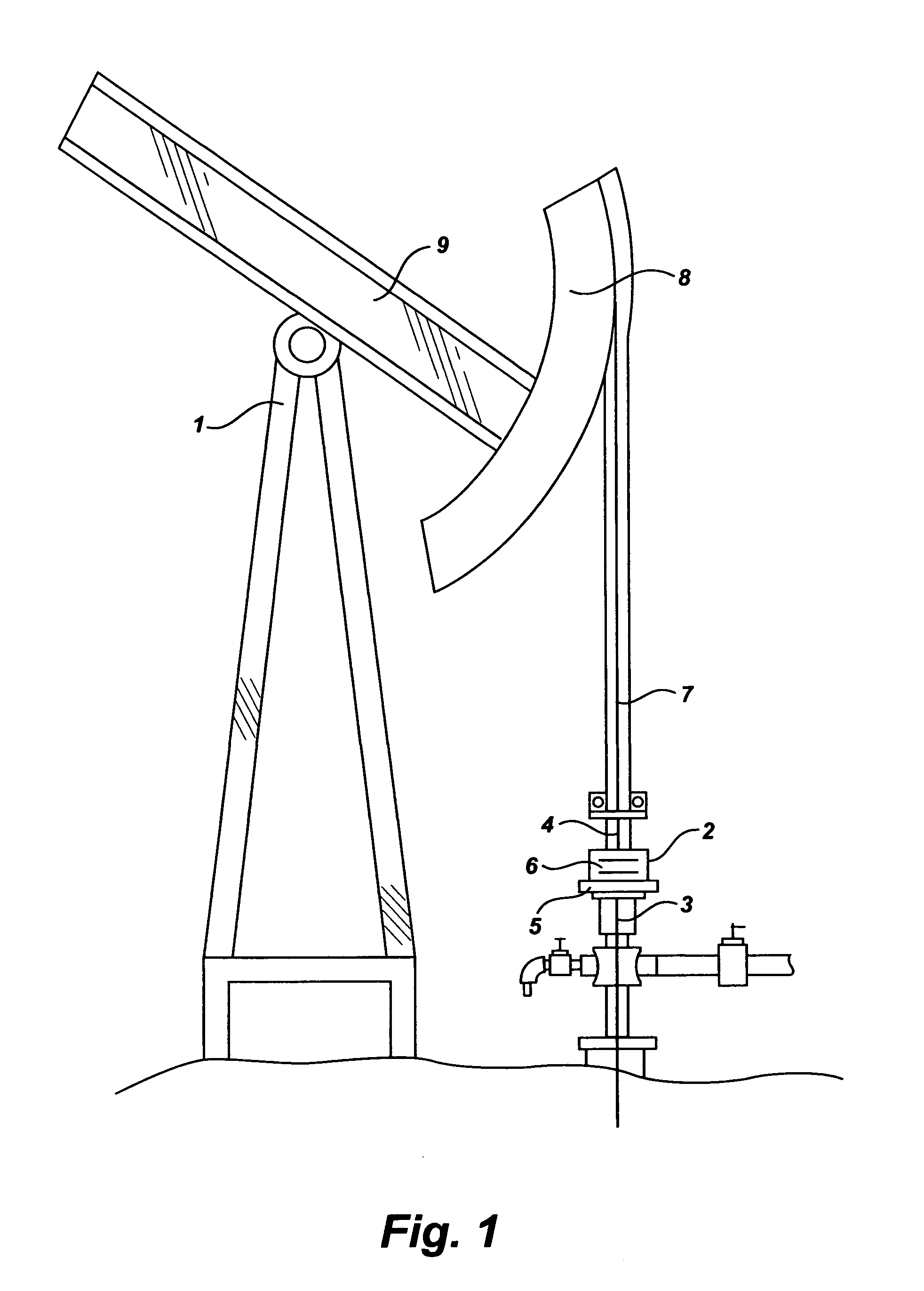
[0040]FIG. 1 shows pumping jack unit (1) with the rod rotator (2) which is installed on wellhead stuffing box (3) and polished rod (4). Main parts (5) and (6) of the rod rotator (2) are in a docked position. Polished rod (4) is hung on a cable (7) which is installed on the head (8) of the arm (9) of the pumping jack unit (1). The pumping jack unit (1) is in the lower dead point.

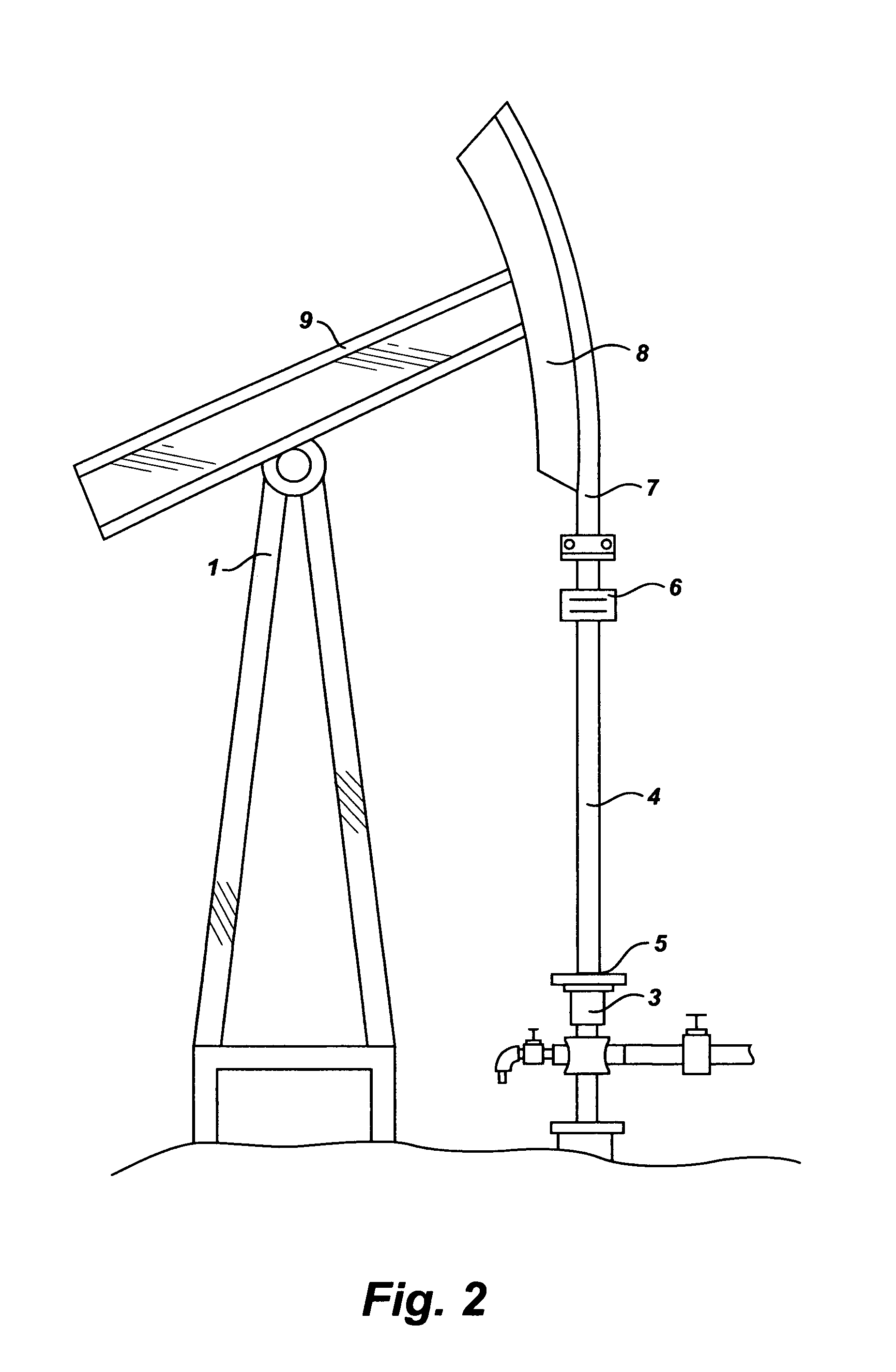
[0041]FIG. 2 shows the position of the pumping jack unit (1) in the upper dead point where the polished rod (4) is fully out of the well. In this position the part (5) remains on the wellhead stuffing box (3), and the part (6) is lifted upwards by the polished rod (4), which demonstrates that the rod rotator is in an undocked position.

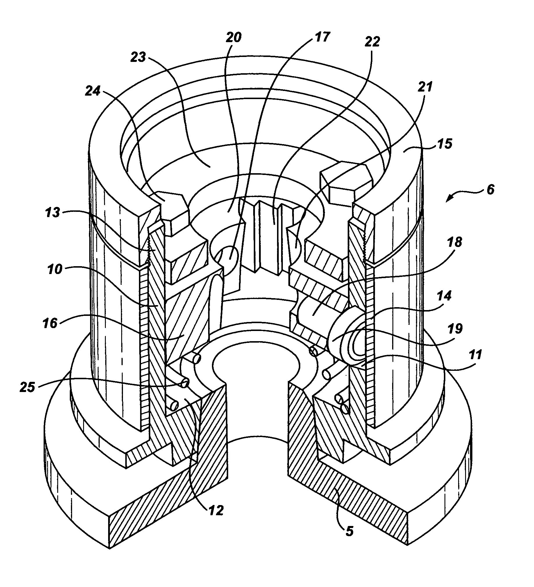
[0042]FIG. 3 shows the rot rotator (2) with its main parts (5) and (6). Both parts (5) and (6) are in a docked position through mutually docking surfaces (8) of the part (5) and (9) of the part (6). Both surfaces (8) and (9) are made in the shape of self-locking (or self-brakin...


PUM


Abstract

A polished rod rotator uses a new method and mechanism to rotate a string of sucker rods relative to a string of oil well tubing to high degrees of rotational angle and achieve large rotator torque. The activation and resulting rotation torque is achieved through axial impact directly by the weight of the sucker rod string at the end of the downward movement of the pumping equipment. The rotator is a two-part assembly, one part is attached to a well-head stuffing box and the other is attached to a polished rod, having a hollow body with spiral slots with rollers. With the downward movement of a beam, the two parts dock through their docking surfaces, while the weight of sucker rods forces the rotator to move down using rollers in spiral slots rotating the polished rod along with the sucker rods until the beam's movement is complete. With the upward movement of the beam, the parts undock rod rotator is static waiting for the completion of pumping cycle.

Description

REFERENCES CITED[0001]U.S. Patent Documents2.178.700November, 1939Penick et al.166 / 782.294.061August, 1942Williamson2.471.198May, 1949Cormany166 / 782.595.434May, 1952Williams2.599.039June, 1952Baker2.630.181March, 1953Solum4.716.961January, 1988Makins, Jr. et al166 / 684.844.171July, 1989Russel, Jr.166 / 784.993.276February, 1991Edwards166 / 785.427.178June, 1995Bland  166 / 78.1BACKGROUND OF THE INVENTION[0002]The present invention is in the field of wellhead equipment and is intended for use in oil wells, where extraction is carried out by using pumping equipment with reciprocating sucker rods. This invention is used to rotate a string of sucker rods during the operation of pumping equipment.[0003]The overwhelming majority of oil wells have either intended or unintended deviation from the vertical axis. Rod rotators and tubing rotators are used in order to decrease the wear of strings of oil well tubings and sucker rods, prevent unwanted unscrewing of sucker rods and reduce the deposit of ...

Claims


Application Information

Patent Timeline
Patent Type & Authority Patents(United States)
IPC IPC(8): E21B19/00
CPCE21B17/1071E21B43/127F04B47/02
Inventor ALI-ZADA, VAGIFALI-ZADE, NARGUIZ
Owner ALI ZADA VAGIF
Why Eureka
Try Eureka