
Subsea clamp for hoses and control lines

Inactive Publication Date: 2011-01-04
INT CLAMPS
View PDF4 Cites 99 Cited by
  • Summary
  • Abstract
  • Description
  • Claims
  • Application Information

AI Technical Summary

Benefits of technology

[0007]Another embodiment of the invention provides a mounting structure which can be used to mount a clamp to a cylindrical object, such as a pipe. The structure comprises a base plate, a hollow post, and a pair of spaced apart walls. The base plate has a first face and a second face. The hollow post extends normally from the first fa

Problems solved by technology

They also have to be reliable in their function, because repairs in the subsea environment are difficult and expensive.

Method used


Image

  • Subsea clamp for hoses and control lines
  • Subsea clamp for hoses and control lines
  • Subsea clamp for hoses and control lines

Examples


Embodiment Construction

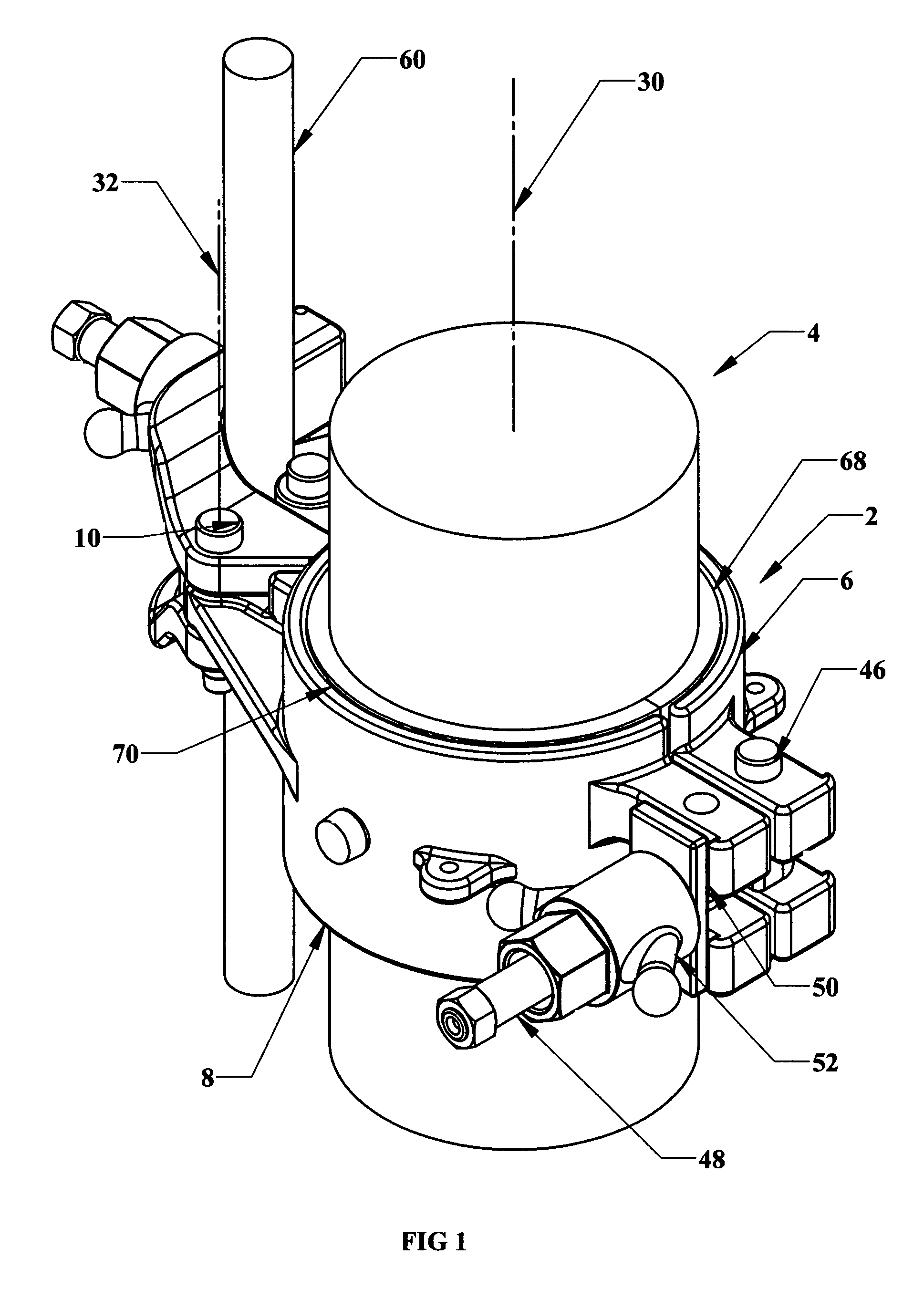
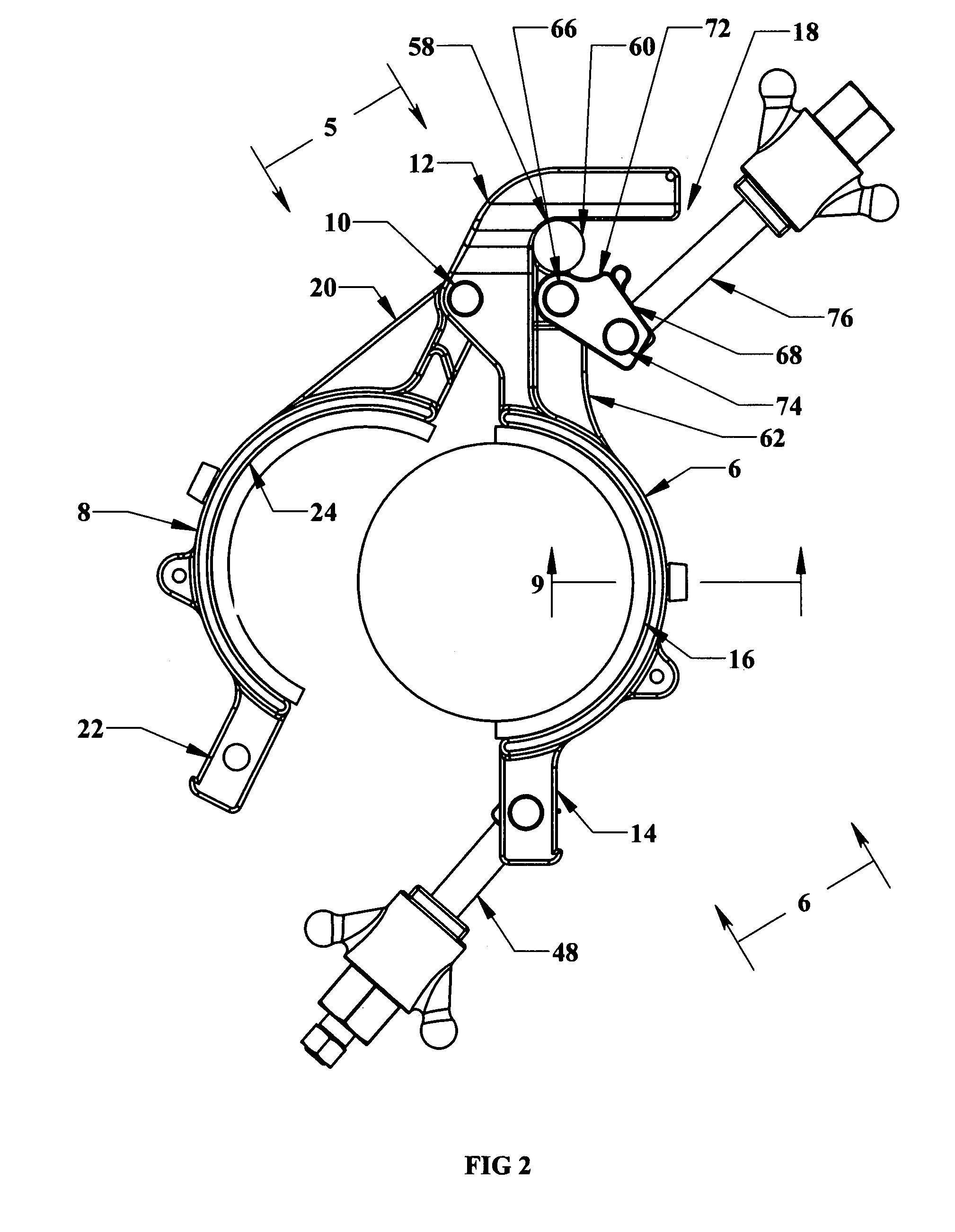
[0019]With reference to FIGS. 1-6 and 9, one embodiment of the invention provides a clamp 2 for a tubular hose or cable 4. The clamp comprises a first clamp half 6, a second clamp half 8, and a hinge pin 10.

[0020]The first clamp half has a first end 12 and a second end 14 and defines a first concave semi-cylindrical face 16. Preferably, the semi-cylindrical face forms about half of an inner cylindrical face. The first end of the first clamp half carries means 18 for mounting the clamp. FIGS. 7-8 show an alternative design wherein a first clamp half 106 carries a means 118 for mounting the clamp. FIGS. 10-11 show an alternative design for a portion of the means 118.

[0021]The second clamp half has a first end 20 and a second end 22 and defines a second concave semi-cylindrical face 24. Preferably, the semi-cylindrical face forms about half of an inside cylindrical face. The first clamp half and the second clamp half come together along a parting line, it being understood that the part...


PUM


Abstract

A clamp for a tubular hose or cable is disclosed. The clamp comprises a first clamp half, a second clamp half, and a hinge pin. The first clamp half has a first end and a second end and defines a first concave semi-cylindrical face. The first end of the first clamp half carries means for mounting the clamp. The second clamp half has a first end and a second end and defines a second concave semi-cylindrical face. The first clamp half and the second clamp half come together along a parting line and are retained together by a hinge pin. The clamp halves are provided with snap-in liners for easy use. Alternative mounts for mounting the clamp on subsea wire line or tubulars is also disclosed.

Description

CROSS REFERENCES TO RELATED APPLICATIONS[0001]This application claims the benefit of U.S. Provisional Application No. 60 / 859,333 filed Nov. 16, 2006, the disclosure of which is incorporated by reference herein.FIELD OF THE INVENTION[0002]This invention relates to a clamp for securing hoses and control lines to a subsea riser structure.BACKGROUND OF THE INVENTION[0003]Subsea clamps for use in the offshore oil and gas industries have to be durable and rugged to withstand the rigors of use. They also have to be reliable in their function, because repairs in the subsea environment are difficult and expensive. It is also desirable that the clamps have few loose parts, because they are handled in an area where dropped parts can be lost overboard. It is further desirable that the clamps be padded, so as to reduce the risk of damaging the hoses and control lines secured by them.OBJECTS OF THE INVENTION[0004]It is an object of the invention to provide a clamp which is well suited for subsea ...

Claims


Application Information

Patent Timeline
IPC IPC(8): F16L3/08
CPCF16L3/1075F16L3/237E21B17/1035Y10T403/7105Y10T403/5753Y10T403/70F16B2/10F16B2/065F16B7/0433E21B19/02F16L1/123F16L3/08F16L3/1025
Inventor MCCLURE, LAWRENCE M.
Owner INT CLAMPS
Features
  • Generate Ideas
  • Intellectual Property
  • Life Sciences
  • Materials
  • Tech Scout
  • Unparalleled Data Quality
  • Higher Quality Content
  • 60% Fewer Hallucinations
Learn More