Prosthetic foot with adjustable heel height

a technology of prosthetic feet and heel heights, applied in the field of prosthetic feet, can solve the problems of preventing users from dropping or relaxing their feet, the prior art adjustment mechanism is relatively complicated, and the heel height cannot be varied

Active Publication Date: 2011-01-04
COLLEGE PARK IND INC
View PDF20 Cites 66 Cited by
  • Summary
  • Abstract
  • Description
  • Claims
  • Application Information

AI Technical Summary

Problems solved by technology

As a consequence, the heel height cannot be varied, and this can present problems when a user switches from one style of shoe to another.
The limitations of the fixed angle also prevent a user from dropping or relaxing his or her foot when sitting.
In general, prior art adjustment mechanisms have been found to be relatively complicated which can make them expensive and difficult to use.

Method used


Image

  • Prosthetic foot with adjustable heel height
  • Prosthetic foot with adjustable heel height
  • Prosthetic foot with adjustable heel height

Examples


Embodiment Construction

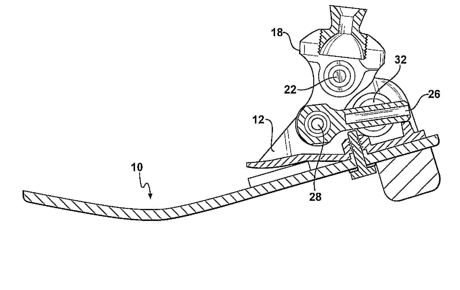
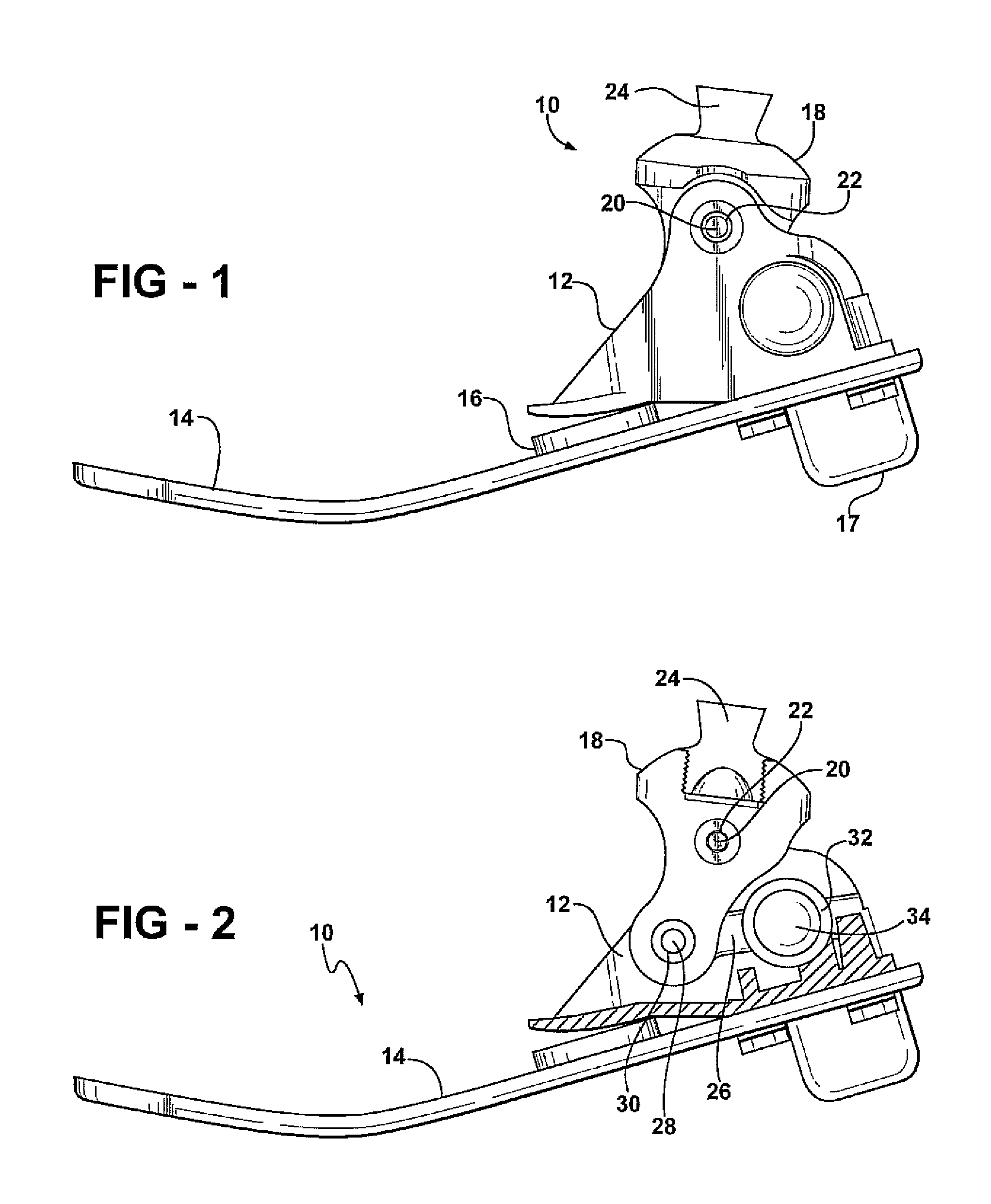
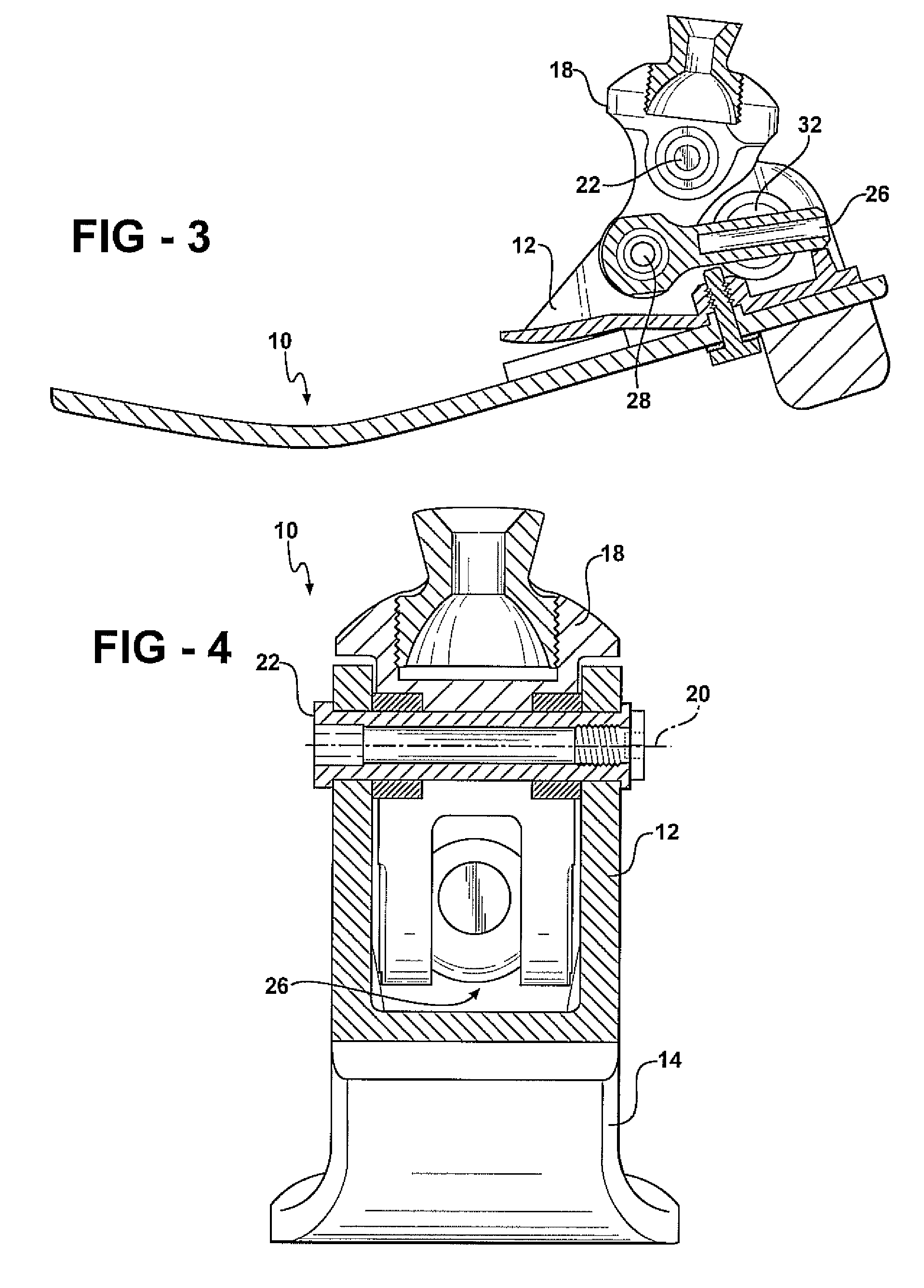
[0016]The present invention is directed to a prosthetic foot with an adjustable height heel. The adjustability is achieved through the use of a particular mechanical assembly employed in connection with a frame portion of a prosthetic foot. The assembly includes an ankle link which is pivotally supported by the frame portion of the foot at a first pivot axis. This ankle link is configured to attach the foot to a prosthetic leg. A detent rod is pivotally connected to the ankle link at a second pivot axis which is spaced from the first pivot axis. A detent member is pivotally affixed to the frame at a third pivot axis. The detent member engages a portion of the detent rod and is operable to selectably retain that rod. By controlling the detent mechanism, the length of the detent rod extending between the second and third pivot points may be changed, and as this length is changed, the ankle link is pivoted back and forth thereby changing the angular relationship of the ankle link and t...


PUM


Abstract

A prosthetic foot having an adjustable height heel includes a frame portion with an ankle link pivotally supported on the frame portion at a first pivot axis. A detent rod is pivotally connected to the ankle at a second pivot axis, and a detent member is pivotally affixed to the frame portion at a third pivot axis. The detent member is selectively operable to receive and releasably retain a length of the detent rod therein so that the length of the detent rod extending between the second and third pivot axes may be selectably adjusted. When the length of the rod is so adjusted, the angular relationship of the frame portion and the ankle link is changed thereby changing the heel height of the foot. The detent mechanism may be activated by various means including fluidic means, mechanical means, electromechanical means, and the like.

Description

CROSS-REFERENCE TO RELATED APPLICATIONS[0001]This application claims priority of U.S. Provisional Patent Application Ser. No. 60 / 811,974 filed Jun. 8, 2006, entitled “Prosthetic Foot with Adjustable Heel Height.”FIELD OF THE INVENTION[0002]This invention relates generally to prosthetic limbs. More specifically, the invention relates to prosthetic feet. Most specifically, the invention relates to a prosthetic foot wherein the heel height is adjustable.BACKGROUND OF THE INVENTION[0003]Most prosthetic feet are configured so that the angle formed between the foot and a prosthetic leg joined thereto is fixed. As a consequence, the heel height cannot be varied, and this can present problems when a user switches from one style of shoe to another. The limitations of the fixed angle also prevent a user from dropping or relaxing his or her foot when sitting.[0004]As a consequence, it will be appreciated that there is a need for a prosthetic foot wherein the angle between the foot and the pylo...

Claims


Application Information

Patent Timeline
Patent Type & Authority Patents(United States)
IPC IPC(8): A61F2/68A61F2/66G05G1/04
CPCA61F2/66A61F2/68Y10T74/20678A61F2002/30359A61F2002/30433A61F2002/305A61F2002/30502A61F2002/5003A61F2002/5009A61F2002/5018A61F2002/502A61F2002/5043A61F2002/5073A61F2002/6642A61F2002/665A61F2002/6671A61F2002/6854A61F2002/701A61F2002/707A61F2002/74A61F2002/741A61F2002/745A61F2002/747A61F2220/0025A61F2220/0033A61F2220/0041A61F2/6607A61F2/70A61F2/74A61F2/741
Inventor DUNLAP, DAVIDTASZREAK, AARONCHRISMAN, LARS R.LEYDET, MICHAEL G.JOHNSON, CHRISTOPHER L.
Owner COLLEGE PARK IND INC
Why Eureka
Try Eureka