

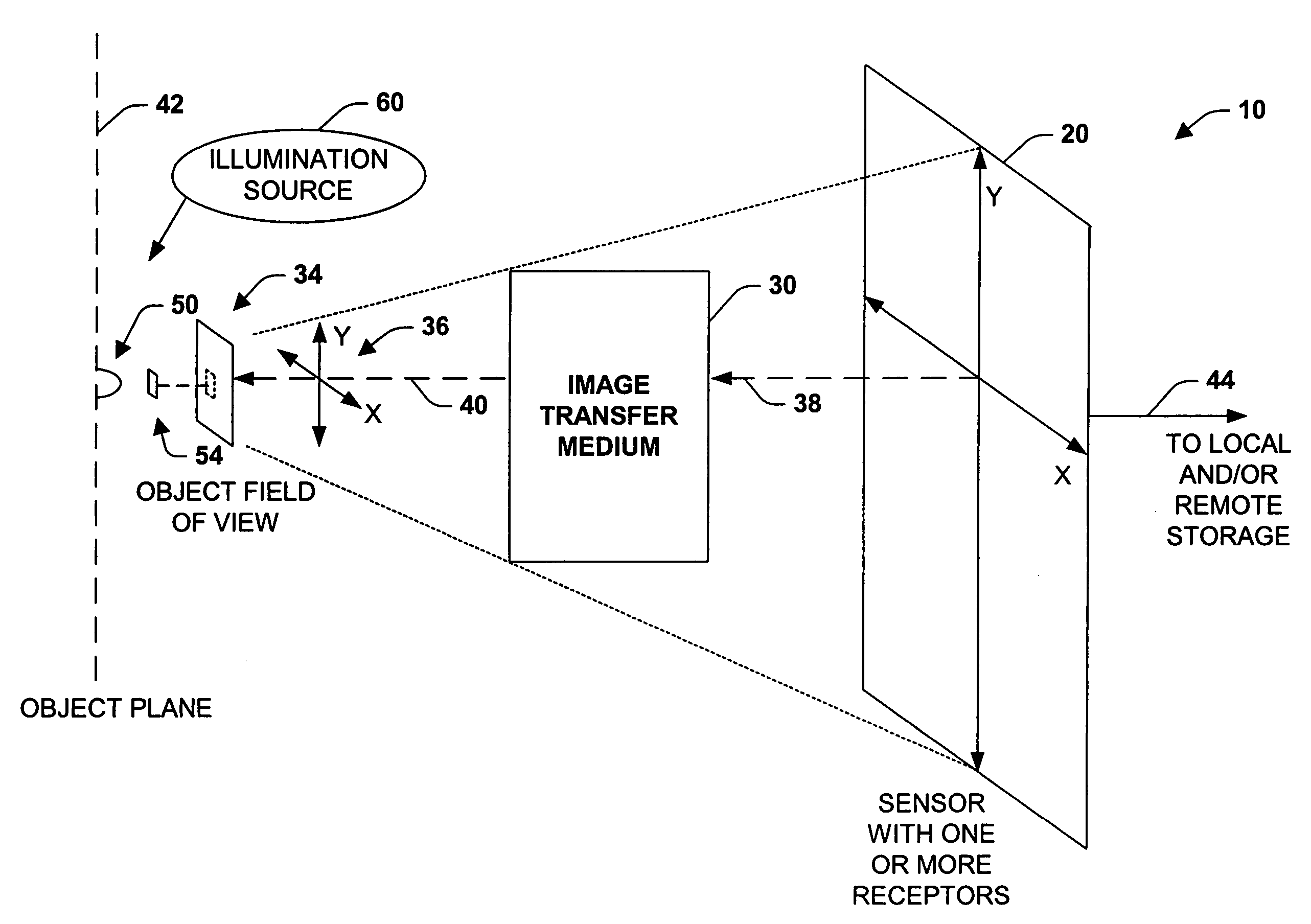
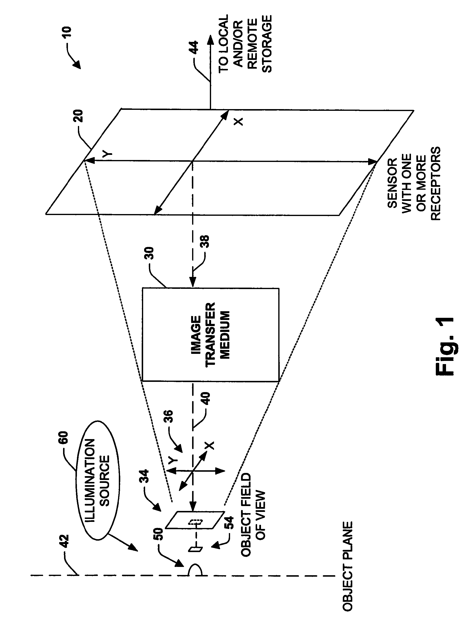
Digital images and related methodologies
a digital image and image technology, applied in the field of digital images and related methodologies, can solve the problems of compromising image resolution and contrast for magnification, not realizing the best physically possible, and rarely, if ever actually, achieving the resolution of such an optical system, etc., and achieve the effect of increasing the signal-to-noise ratio
- Summary
- Abstract
- Description
- Claims
- Application Information
AI Technical Summary
Benefits of technology
Problems solved by technology
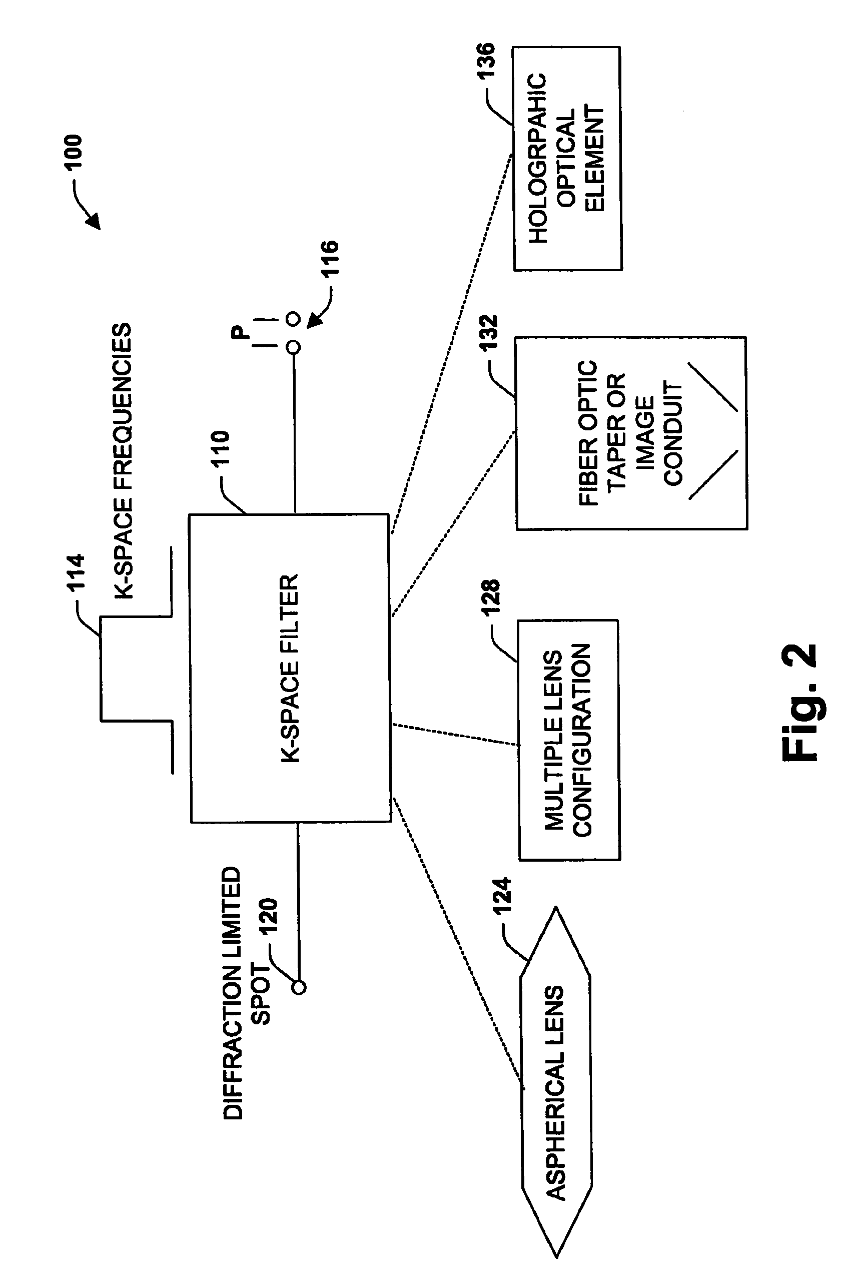
Method used
Image

Examples
example present invention
Optical Parameters
[0330]
ResolutionNADOFWDMag2,500 nm0.10 100 um125 mm 1x1,000 nm0.25 16 um48 mm3x 625 nm0.406.25 um28 mm4x 384 nm0.652.40 um14 mm7x
Conventional Microscope Optical Parameters
[0331]
Mag Req'd forResolutionNADOFWDresolution (10x eyepiece)2,500 nm0.10 100 um125 mm 100x1,000 nm0.25 16 um48 mm250x 625 nm0.406.25 um28 mm400x 384 nm0.652.40 um14 mm650x
[0332]To achieve a resolution of 2,500 nm, the Conventional Microscope requires a 100× magnification and thus has a resolution performance of 1 / 100 of that of the imaging system of the present invention. To achieve a resolution of 2,500 nm, the Conventional Microscope requires a 100× magnification and thus has a, resolution performance of 1 / 80 of that of the imaging system of the present invention. To achieve a resolution of 2,500 nm, the Conventional Microscope requires a 100× magnification and thus has a resolution performance of 1 / 100 of that of the imaging system of the present invention. To achieve a resolution of 384...
PUM
 Abstract
Description
Claims
Application Information