Check patentability & draft patents in minutes with Patsnap Eureka AI!

Joy stick

a technology of joysticks and sticks, applied in the field of joysticks, can solve the problems of high cost, unfavorable operation feeling, and high durability, and achieve the effect of durable and long-life structure, downsizing

Inactive Publication Date: 2011-02-08
MITSUMI ELECTRIC CO LTD
View PDF5 Cites 0 Cited by
  • Summary
  • Abstract
  • Description
  • Claims
  • Application Information

AI Technical Summary

Benefits of technology

The invention is a joy stick with a small, durable, and long-life structure. It solves the problem of burrs causing issues even when using a metal-made upper casing. The joy stick comprises a first casing made of metal with a cutout portion, a second casing made of resin, and a pivot member made of metal and placed between the first and second casings. The pivot shaft is supported by a part of the first casing other than the edge of the cutout portion. The cutout portion has an inclined inner face, and the pivot shaft has a line contact with the inclined inner face. This design ensures smooth operation and durability of the joy stick.

Problems solved by technology

The damaged outer peripheral surface may disturb pivoting and may cause the uncomfortable operation feeling.
For this reason, management of press working is required so as not to form burrs, so that the cost becomes high.
In addition, both the upper casing and the lower casing may conceivably be made of a resin material to eliminate the occurrence of the burrs, but a problem occurs in terms of durability unless the entire upper casing is formed firmly by being provided with a sufficient thickness.
If the entire upper casing is provided with the sufficient thickness, a shape of the entire upper casing becomes large, so that a downsizing of the joy stick becomes difficult.
In this fixing structure, however, since the joy stick is fixed at only one spot, the board maybe broken when excessive force is applied to a screwed portion during the operation.

Method used


Image

  • Joy stick
  • Joy stick
  • Joy stick

Examples


Embodiment Construction

Embodiments of the invention will be discussed in detail with reference to the accompanying drawings.

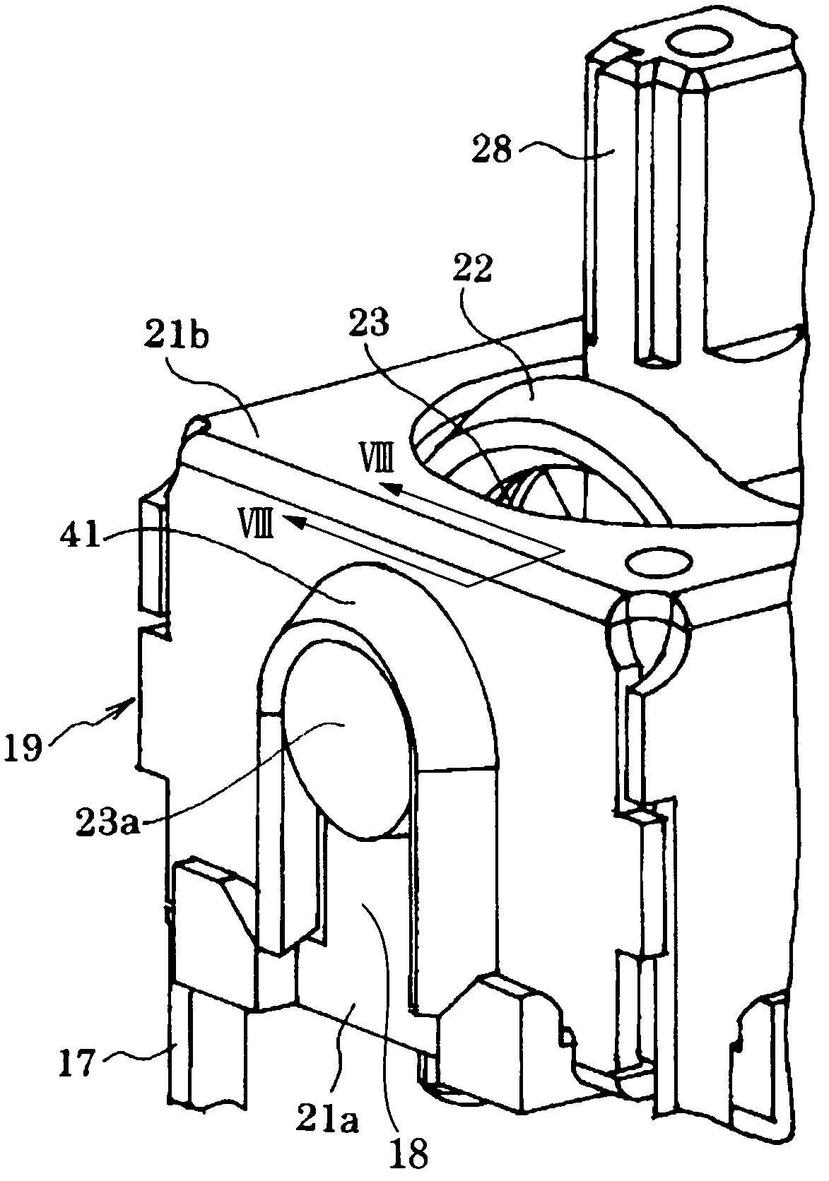
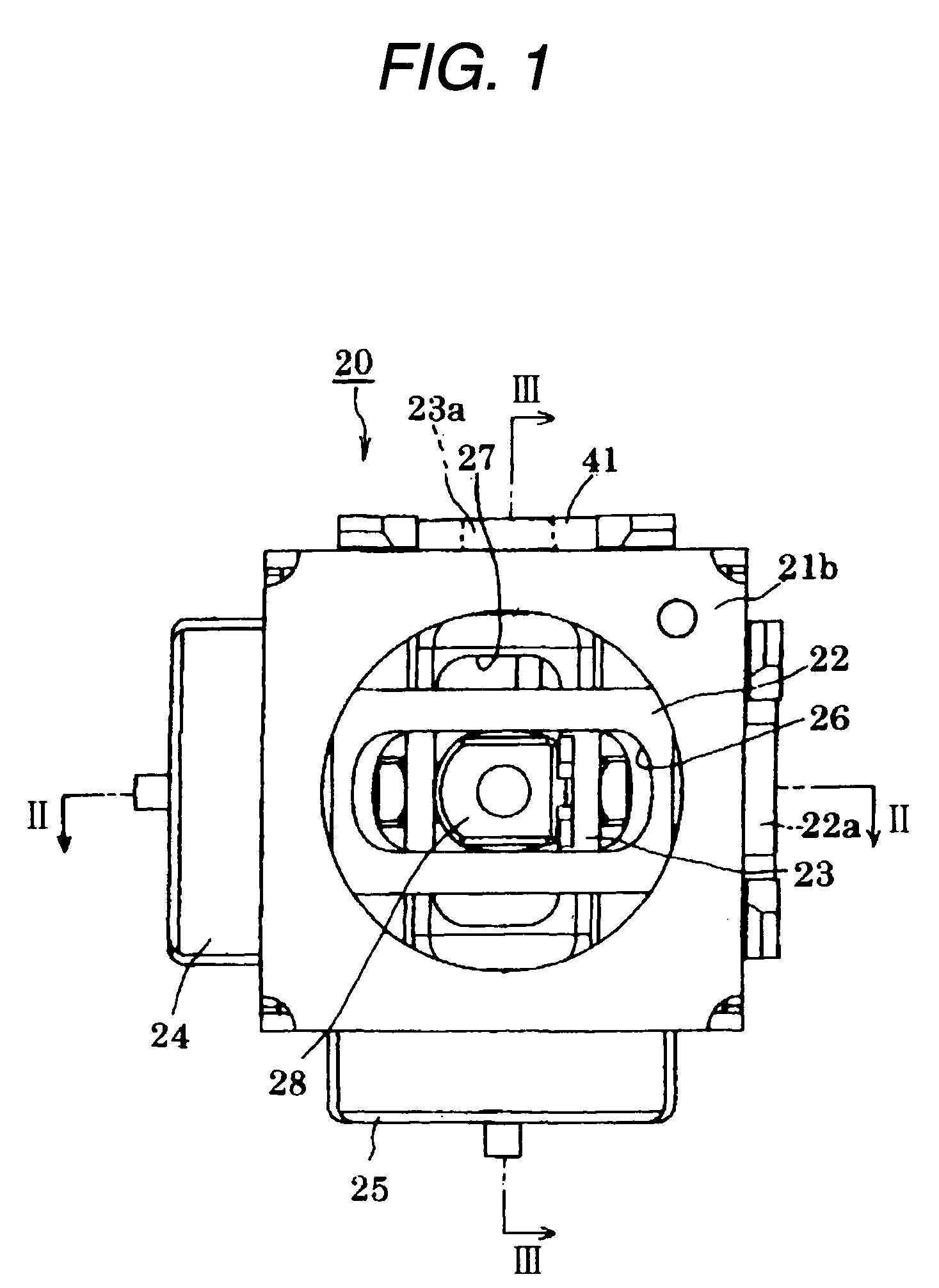
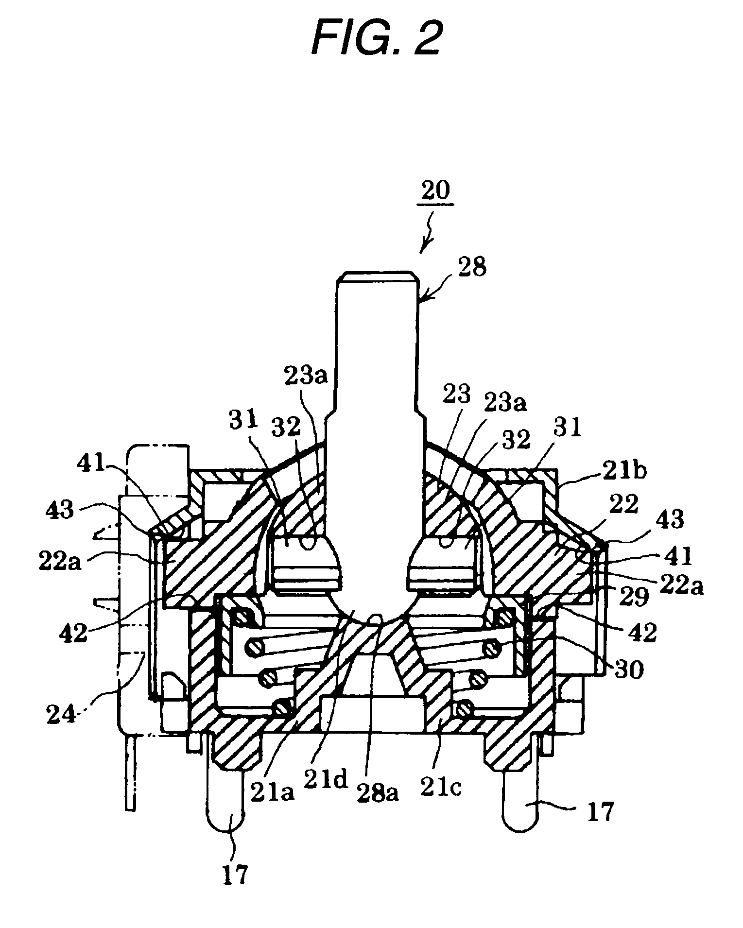
As shown in FIGS. 1 to 3, a joy stick 20 comprises an upper casing 21b and a lower casing 21a which is engaged with the upper casing 21a. The upper casing 21b and the lower casing 21a form a box-shaped casing body 21.

The lower casing 21a is comprised of a resin. An upper arm 22 and a lower arm 23 are disposed pivotably perpendicular to each other inside the lower casing 21a.

The upper casing 21b is manufactured by press working, and mounting projections 17 are integrally provided at four corner positions on a lower end portion of the upper casing 21b in a state of being extended straightly downward. When the joy stick 20 is mounted on a board (not shown), these mounting projections 17 are inserted into holes provided in the board so that the joy stick 20 is fixed to the board.

In each of the side faces of the upper casing 21b, a cutout portion 18 is formed so as to extend from a lower...


PUM


Abstract

A first casing is comprised of metal and has a side face formed with a cutout portion. A second casing is comprised of resin. A pivot member has a pivot shaft and is disposed between the first casing and the second casing so as to be pivotable about the pivot shaft. The pivot shaft is rotatably supported by a part of the first casing which is other than an edge of the cutout portion.

Description

BACKGROUND OF THE INVENTIONThe present invention relates to a joy stick.As shown in FIG. 9, a related-art joy stick 9 comprises an upper casing 1; a lower casing 2 engaged with the upper casing 1; a box-shaped casing body 3 formed by coupling the upper casing 1 and lower casing 2; a pair of upper and lower pivot members 4 and 5 disposed so as to be pivotable perpendicularly to each other inside the casing body 3; an operating member 8 having one end portion extending to an outside of the casing body 3 through a pair of slots 6 and 7 respectively formed in the pivot members 4 and 5 so as to extend in longitudinal directions thereof; and a spring (not shown) for urging the pair of pivot members 4 and 5 to place them in their neutral positions, a pair of signal output devices (not shown) operable to output signals corresponding to respective pivoted angles of the pivot members 4 and 5 pivot (see Japanese Patent Publication No. 2003-223276A).In the related-art joy stick, the upper casin...

Claims


Application Information

Patent Timeline
Patent Type & Authority Patents(United States)
IPC IPC(8): G06F3/033
CPCG05G9/047G05G2009/04718
Inventor ISHIMARU, HIROSHI
Owner MITSUMI ELECTRIC CO LTD
Features
  • R&D
  • Intellectual Property
  • Life Sciences
  • Materials
  • Tech Scout
  • Unparalleled Data Quality
  • Higher Quality Content
  • 60% Fewer Hallucinations
Learn More