
Eyeglasses leg mount structure

a leg mount and eyeglass technology, applied in the field of eyeglasses leg mount structures, can solve the problems of eyeglasses not coming, relatively uneasy user removal and replacement of eyeglasses legs, and inconvenient use for users

Active Publication Date: 2011-03-01
T LINK PPE
View PDF3 Cites 14 Cited by
  • Summary
  • Abstract
  • Description
  • Claims
  • Application Information

AI Technical Summary

Benefits of technology

[0006]Therefore, it is a primary objective of the present invention to provide an eyeglasses leg mount structure, and the installation of a connecting unit and a leg mount unit on both sides of the eyeglasses frame allows users to make an angle adjustment and position an eyeglasses leg or eyeglasses strap, and to remove the eyeglasses leg or eyeglasses strap from the connecting unit directly for a repair or replacement, and thus the structure can achieve the effect of meeting different wearing requirements.
[0008]The eyeglasses leg mount structure of the present invention can achieve the effects of making an angle adjustment and positioning the eyeglasses legs or the eyeglasses strap by the connecting unit and the leg mount unit, and also allowing users to remove the eyeglasses legs or the eyeglasses strap from the connecting unit directly for a repair or a replacement to satisfy different wearing requirements.

Problems solved by technology

Furthermore, the conventional eyeglasses do not come with any design of an adjusting structure to allow users to make adjustments to the eyeglasses legs appropriately to cope with various wearing requirements.
Obviously, it is relatively uneasy and inconvenient for users to remove and replace the eyeglasses leg.

Method used


Image

  • Eyeglasses leg mount structure
  • Eyeglasses leg mount structure
  • Eyeglasses leg mount structure

Examples


Embodiment Construction

[0025]The objects, characteristics and effects of the present invention will become apparent with the detailed description of preferred embodiments and the illustration of related drawings as follows.

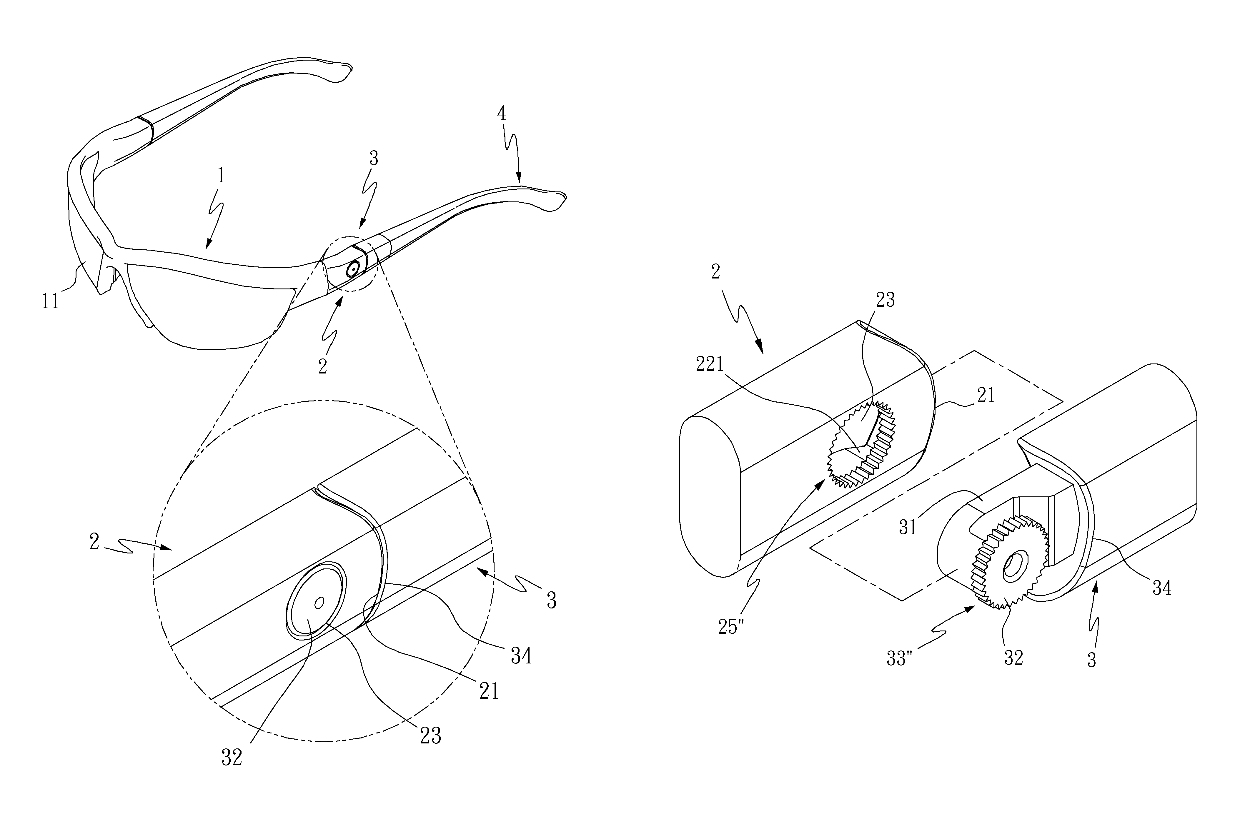
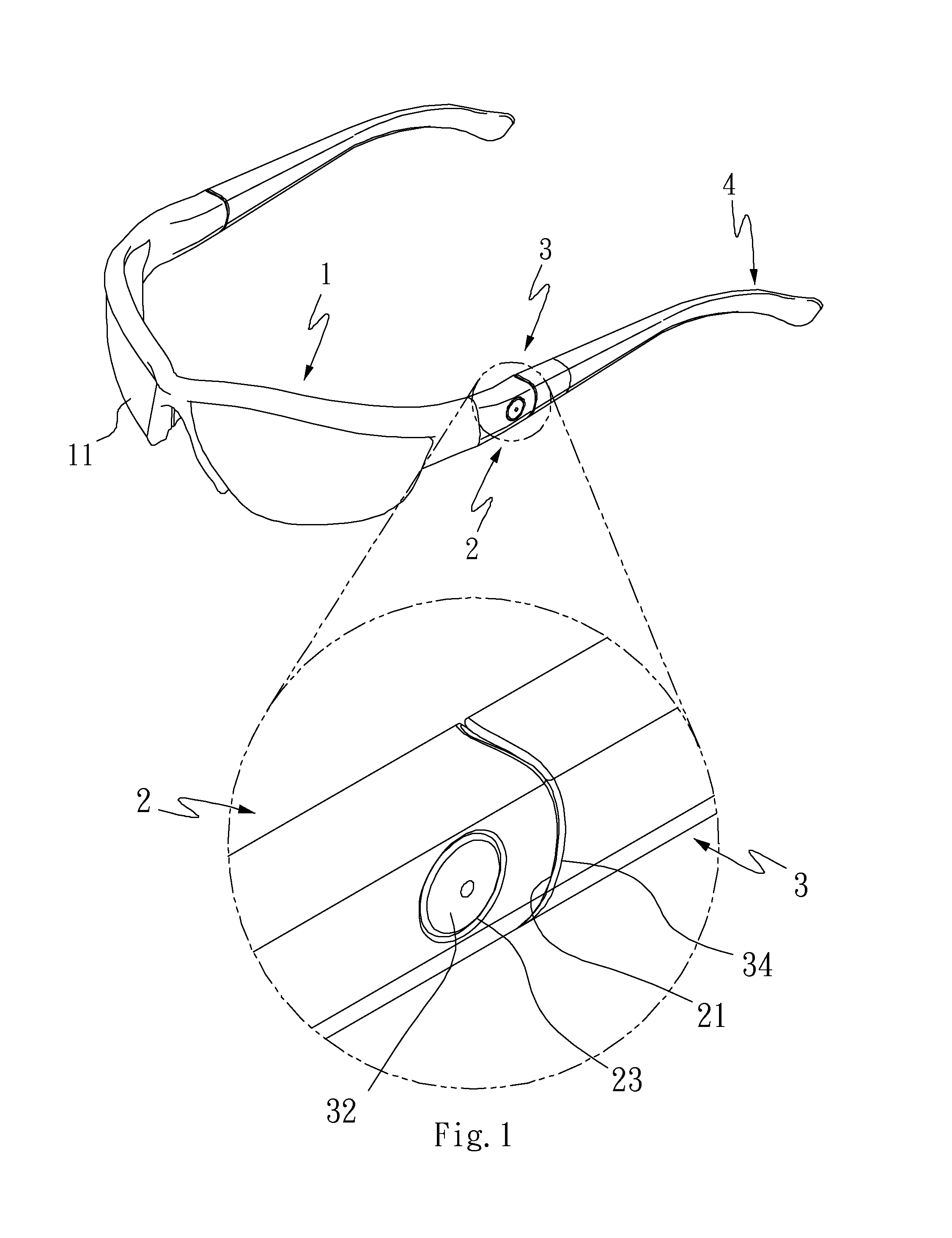
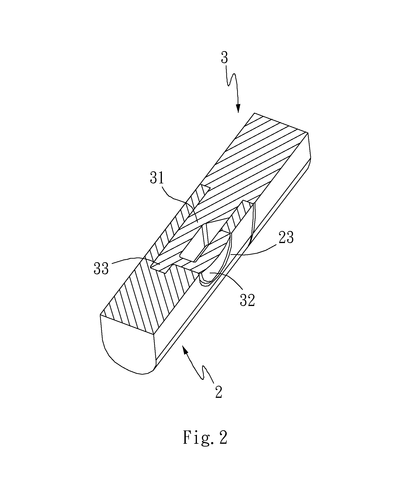
[0026]With reference to FIGS. 1 to 9 for a first perspective view of an application, a first cross-sectional view, first to fourth exploded views, a second cross-sectional view, a cross-sectional view of a using status, and a fifth exploded view of an eyeglasses leg mount structure in accordance with a first preferred embodiment of the present invention respectively, the eyeglasses leg mount structure comprises two connecting units 2 and two leg mount units 3.

[0027]Each of the two connecting units 2 is movably installed on a side of an eyeglasses frame 1, and the eyeglasses frame 1 includes a lens 11, and each connecting unit 2 includes an insert slot 22 interconnected to a distal surface of the connecting unit 2 and inwardly tapered from the distal surface of the connecting unit 2, and...


PUM


Abstract

An eyeglasses leg mount structure includes two connecting units, each movably installed on an eyeglasses frame and each interconnected to an insert slot, wherein the insert slots are tapered inwardly from distal surfaces of the connecting units, and a shaft hole is formed on each connecting unit and interconnected to the insert slot, and each connecting unit includes an interfering portion; and two leg mount units, each having a pair of connecting parts disposed at an end of the connecting unit and inserted into the insert slot, wherein each leg mount unit includes an elastic plate installed on a side of the connecting part and pivotally coupled to the shaft hole, and each leg mount unit includes a latch portion corresponding to the interfering portion, so as to allow users to adjust the eyeglasses and remove eyeglasses legs or an eyeglasses strap conveniently.

Description

FIELD OF THE INVENTION[0001]The present invention relates to an eyeglasses leg mount structure, in particular to an eyeglasses leg mount structure capable of making an angle adjustment and positioning the eyeglasses legs of a pair of eyeglasses, such that the eyeglasses legs or an eyeglasses strap can be removed directly from a connecting unit to meet different wearing requirements.BACKGROUND OF THE INVENTION[0002]A pair of conventional eyeglasses is mainly composed of an eyeglasses frame, two eyeglasses legs, a clamp portion having a through hole and disposed separately on both sides of the eyeglasses frame, a pivot portion disposed at an end of each eyeglasses leg and coupled to the clamp portion, and a fixing hole formed on the pivot portion and corresponding to the through hole. The through hole and the fixing hole are coupled with each other by a fixing element, so that each eyeglasses leg is movably and separately coupled to both sides of the eyeglasses frame, and users can sp...

Claims


Application Information

Patent Timeline
Patent Type & Authority Patents(United States)
IPC IPC(8): G02C5/14
CPCG02C3/003G02C5/2263G02C2200/04G02C2200/18
Inventor LIN, KUO-TSENG
Owner T LINK PPE
Learn More