Stackable structural reactor

a structural reactor and stacking technology, applied in the direction of catalytic material combustion, gas-gas reaction process, separation process, etc., can solve the problems of reducing the capacity of the reactor, not performing particularly well near the center of the reactor, and limiting the throughput that can be accommodated

Active Publication Date: 2011-03-15
JOHNSON MATTHEY PLC
View PDF20 Cites 51 Cited by
  • Summary
  • Abstract
  • Description
  • Claims
  • Application Information

AI Technical Summary

Problems solved by technology

An inherent problem with reactors of this kind is that they do not perform particularly well near the center of the reactor.
This problem reduces the capacity of the reactor, effectively limiting the throughput that can be accommodated at the desired level of conversion.
Another problem encountered with reactors installed in cylindrical tubes is that of metallic creep and thermal expansion.
The pressure creates a large hoop stress, which the tube material has difficulty resisting at the high temperature.
Even a few millimeters of growth in the tube diameter creates an undesirable gap between the reactor and the surrounding tube.
Such creep will cause a significant drop in performance.

Method used


Image

  • Stackable structural reactor
  • Stackable structural reactor
  • Stackable structural reactor

Examples


Embodiment Construction

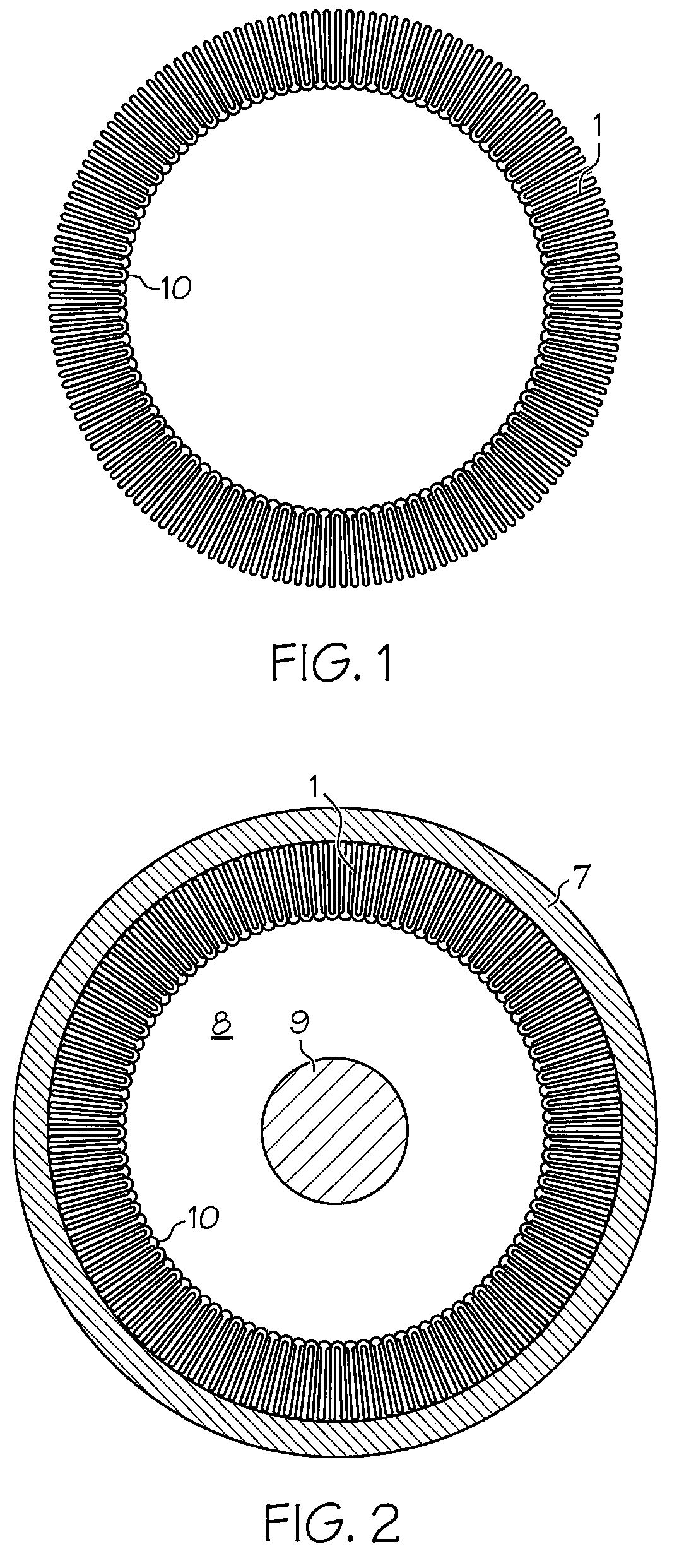
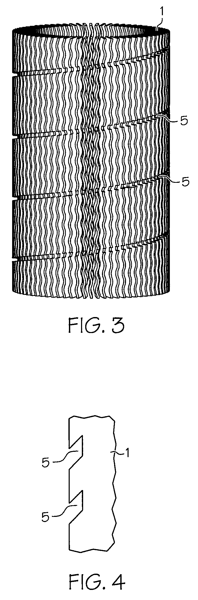
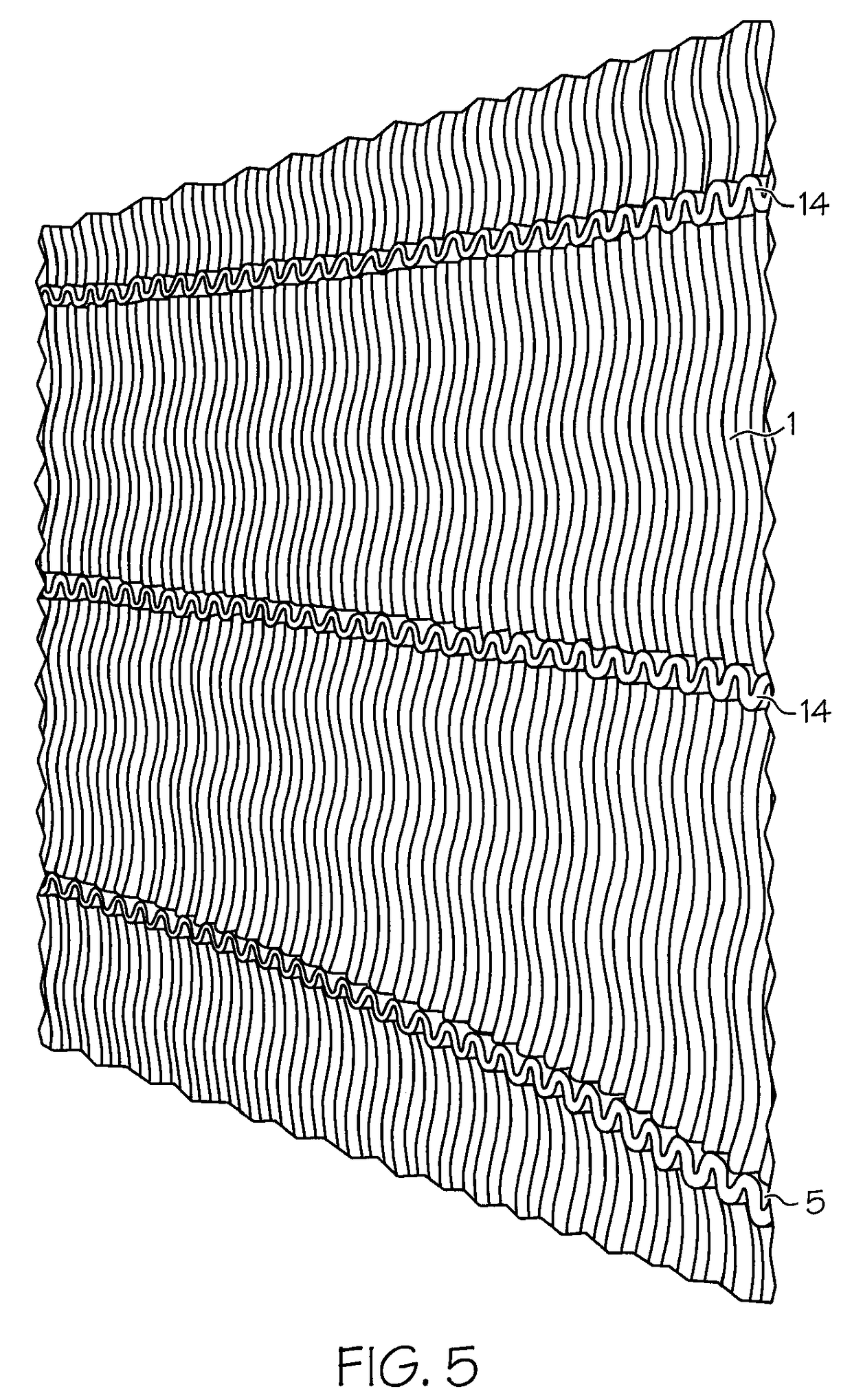
[0039]The reactor of the present invention, sometimes referred to as a stackable structural reactor (“SSR”), comprises a catalyst or reaction support, preferably made of metal foil, the metal foil comprising a plurality of leaves or fins which define a relatively large surface area for catalytic reaction and / or heat exchange. In a preferred embodiment, the fins are formed by folding metal foil back and forth upon itself to define a monolith. The terms “leaves” and “fins” are used interchangeably in this specification. If the monolith is used for catalytic reactions, its surfaces can be coated with a suitable catalyst. The fins can be formed around a center support such as a central mandrel, pipe, post, link piece or other structure in an annular arrangement in order to form a monolith of general annular cross section, as viewed in the direction of the flow of fluid through the reactor. The monolith and central structure can be inserted within a cylindrical tube or outer tube 7, such...


PUM

PropertyMeasurementUnit
temperaturesaaaaaaaaaa
pressuresaaaaaaaaaa
angleaaaaaaaaaa

Abstract

A reactor including a monolith having a plurality of fins in an annular arrangement for receiving fluid flow through the reactor. The monolith is disposed within a generally cylindrical outer tube, and around a corrugated inner tube. The reactor includes a device for urging the monolith radially outward, so as to maintain contact between the monolith and the outer tube.

Description

CROSS-REFERENCE TO RELATED APPLICATIONS[0001]This application claims the benefit of U.S. Provisional Patent Application Ser. No. 60 / 874,901 filed Dec. 14, 2006, the contents of which are incorporated herein by reference in their entirety.BACKGROUND OF THE INVENTION[0002]This invention relates to the field of surface catalytic reactions and / or heat exchange. The present invention provides a reactor (sometimes referred to as Stackable Structural Reactor or SSR) which fits within a cylindrical tube, and which effectively transfers heat from the tube to the interior of the reactor, or from the interior of the reactor to the tube.[0003]The reactor and improvements thereof of the present invention achieve similar objectives as those of the catalyst supports described in U.S. Pat. App. Pub. Nos. 2007 / 0025893, 2006 / 0263278, 2006 / 0245982, 2006 / 0245981, 2006 / 0230613, 2006 / 0228598, 2006 / 0019827 and 2006 / 0008414 and U.S. Pat. Nos. 7,150,099 and 6,920,920, the contents of which are incorporated ...

Claims


Application Information

Patent Timeline
Patent Type & Authority Patents(United States)
IPC IPC(8): B01D50/00B01D53/34
CPCB01J10/007B01J19/242B01J19/244B01J19/2485F23C13/00B01J12/007Y10T29/49938B01J2219/00094B01J2219/2408B01J2219/2411B01J2219/2419B01J2219/2428B01J2219/2434B01J2219/2443B01J2219/2448F28F1/40Y10T29/49352Y10T29/49345Y10T29/49872
Inventor WHITTENBERGER, WILLIAM A.BECKER, DAVID A.BARTOS, RANDALL J.
Owner JOHNSON MATTHEY PLC
Why Eureka
Try Eureka