
Electrical terminal

a technology of electrical terminals and terminals, applied in the direction of fixed connections, electrical discharge lamps, coupling device connections, etc., can solve the problem of form tolerance and drawback, and achieve the effect of reducing the height tolerance of electrical terminals

Inactive Publication Date: 2011-04-12
HON HAI PRECISION IND CO LTD
View PDF7 Cites 24 Cited by
  • Summary
  • Abstract
  • Description
  • Claims
  • Application Information

AI Technical Summary

Benefits of technology

The design effectively reduces height tolerance, improving the alignment and appearance of the connector by accommodating manufacturing variations and ensuring consistent engagement with the PCB.

Problems solved by technology

However, the drawback still occurs for the reason of the form tolerance.

Method used


Image

  • Electrical terminal
  • Electrical terminal
  • Electrical terminal

Examples


Embodiment Construction

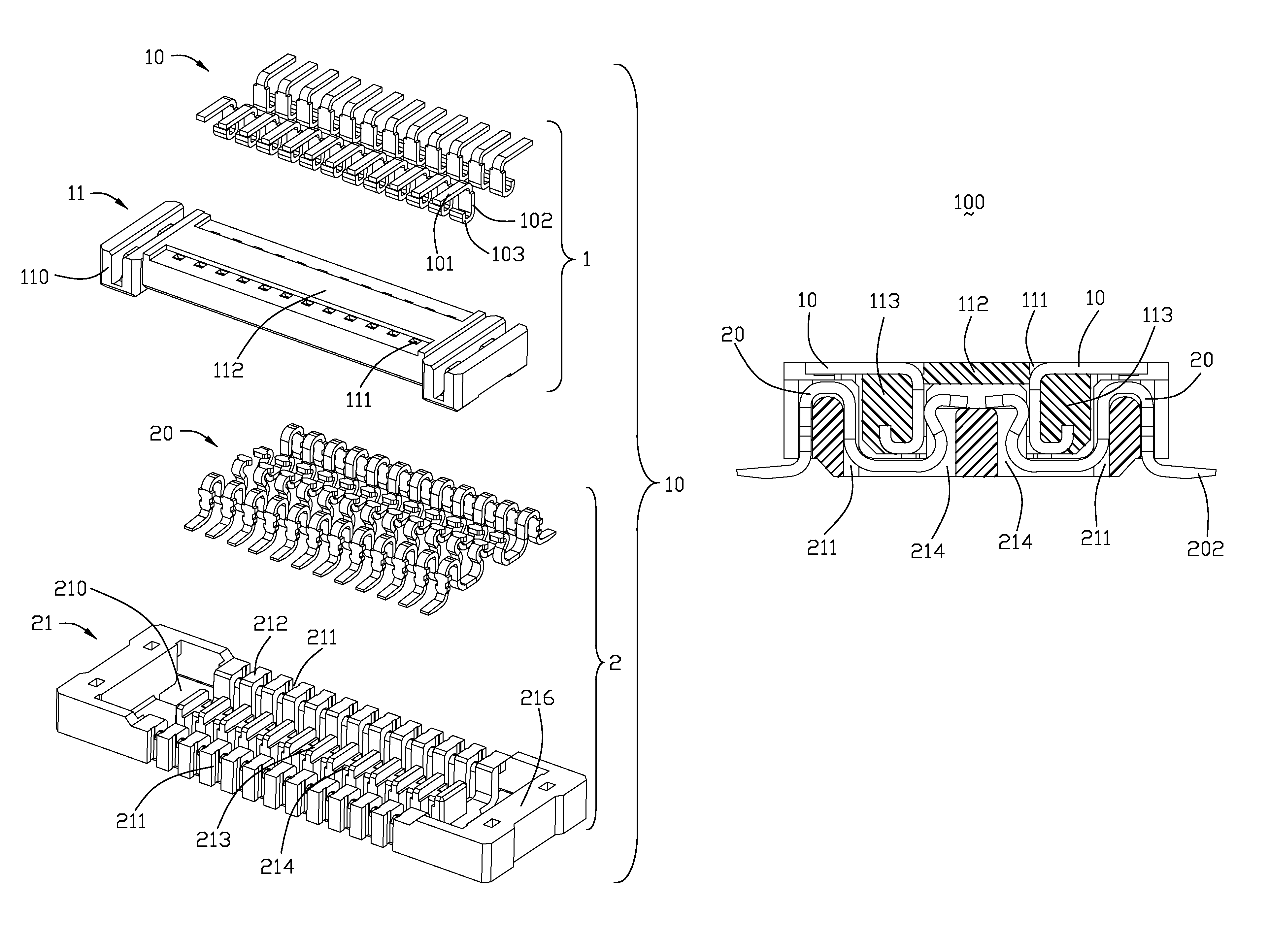
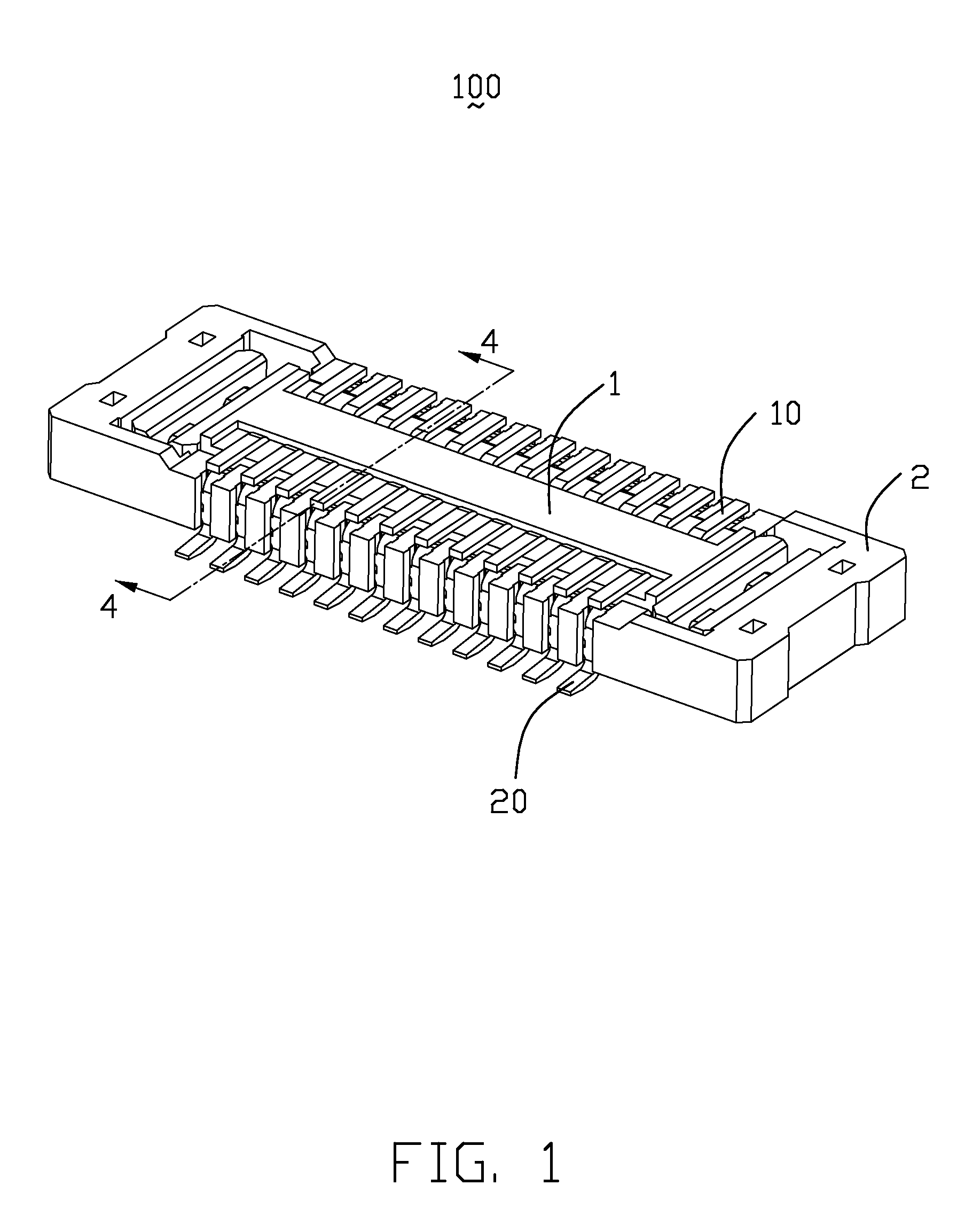
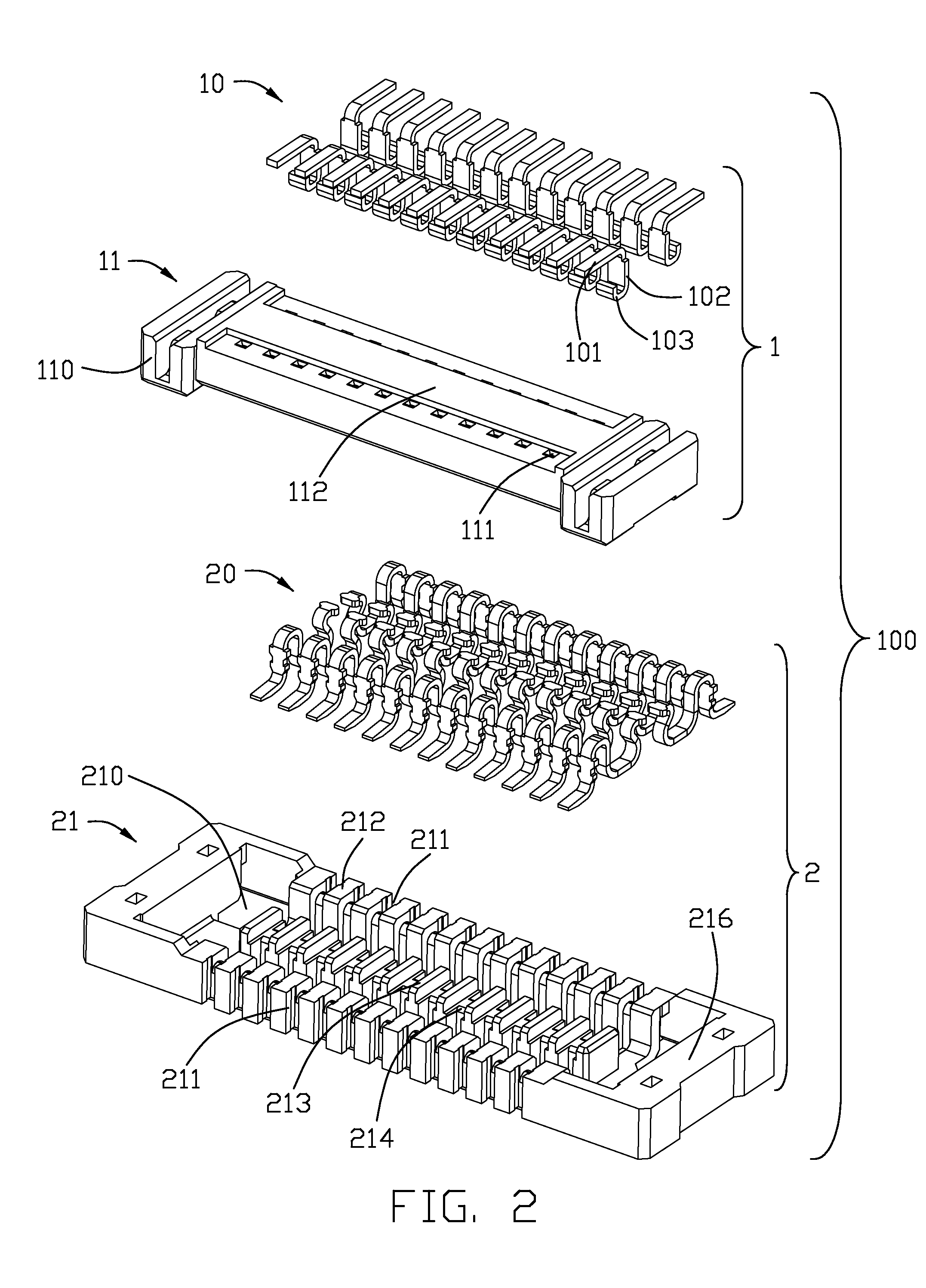
[0014]Referring to FIGS. 1 and 2, the present invention relates to a plurality of electrical terminals 20 received in a first insulative housing 21. The plurality of electrical terminals 20 and the first insulative housing 21 constitute to a receptacle connector 2. The receptacle connector 2 is used to receive a plug connector 1. The plug connector 1 comprises a second insulative housing 11 and a plurality of contacts 10 received in the second insulative housing 11.

[0015]Referring to FIG. 2, the first insulative housing 21 includes a pair of longitudinal walls 212, a pair of transverse walls 216, a receiving cavity 210 surrounded by the pair of longitudinal walls 212 and transverse walls 216, and a tongue board 213 extending from a bottom wall (not labeled). The pair of longitudinal walls 212 define a plurality of first passageways 211, and the tongue board 213 has a plurality of second channels 214 according to the first passageways 211.

[0016]Referring to FIGS. 3 and 5, the electri...


PUM


Abstract

An electrical terminal (20) used with board-mounted connector (2) having a housing comprising (21): a fixing portion, a contacting portion (204) and a soldering portion (202). The fixing portion defines barbs formed along opposite edges thereof for securing the terminal within the housing, the contacting portion (204) extends from on side of the fixing portion and the soldering portion extends away from the other side of the fixing portion. The soldering portion (202) extends obliquely towards a circuit board on which the connector (2) is mounted, the soldering portion having a tip end with a reduced thickness thereof.

Description

BACKGROUND OF THE INVENTION[0001]1. Field of the Invention[0002]The present invention relates to an electrical terminal, and in particular to an electrical terminal used in a board-mounted connector.[0003]2. Description of Prior Arts[0004]Traditionally, electrical terminals are arranged in an insulative housing to form a connector. The terminal defines a soldering portion. The soldering portion extends externally from the insulative housing for soldering to a print circuit board (PCB) of another electrical apparatus. Usually, the soldering portion is designed parallel to the PCB. While, in application, due to manufacturing tolerance, the soldering portion will extend obliquely toward or away from the PCB. When a plurality of soldering portions extend obliquely away from the PCB, the plurality of soldering portions can not be aligned in a plane parallel to the PCB. this situation will influence the outlook of the connector. In order to resolve such problem, the soldering portion are ...

Claims


Application Information

Patent Timeline
Patent Type & Authority Patents(United States)
IPC IPC(8): H01R12/00
CPCH01R12/714H01R12/57
Inventor LIAO, CHI-NAN
Owner HON HAI PRECISION IND CO LTD
Learn More