Method and apparatus for a tunable channelizing patch antenna

a patch antenna and channelizing technology, applied in the field of wide band antennas, can solve the problems of limited usefulness in certain applications, inability to adjust the tunable band of the antenna, and inability to adjust the tunable band,

Active Publication Date: 2011-04-19
ALCATEL-LUCENT USA INC
View PDF8 Cites 14 Cited by
  • Summary
  • Abstract
  • Description
  • Claims
  • Application Information

AI Technical Summary

Problems solved by technology

Although patch antennas offer the above-mentioned benefits, the bandwidth of existing patch antennas is generally limited by the chosen dimensions of the patch.
This makes many existing patch antenna designs inherently narrow band in their operation, and have limited usefulness in certain applications.

Method used


Image

  • Method and apparatus for a tunable channelizing patch antenna
  • Method and apparatus for a tunable channelizing patch antenna
  • Method and apparatus for a tunable channelizing patch antenna

Examples


Embodiment Construction

[0018]Various embodiments will be primarily described within the context of a tunable patch antenna, however, those skilled in the art and informed by the teachings herein will realize that various embodiments are also applicable to other antenna geometries and RF tuning applications.

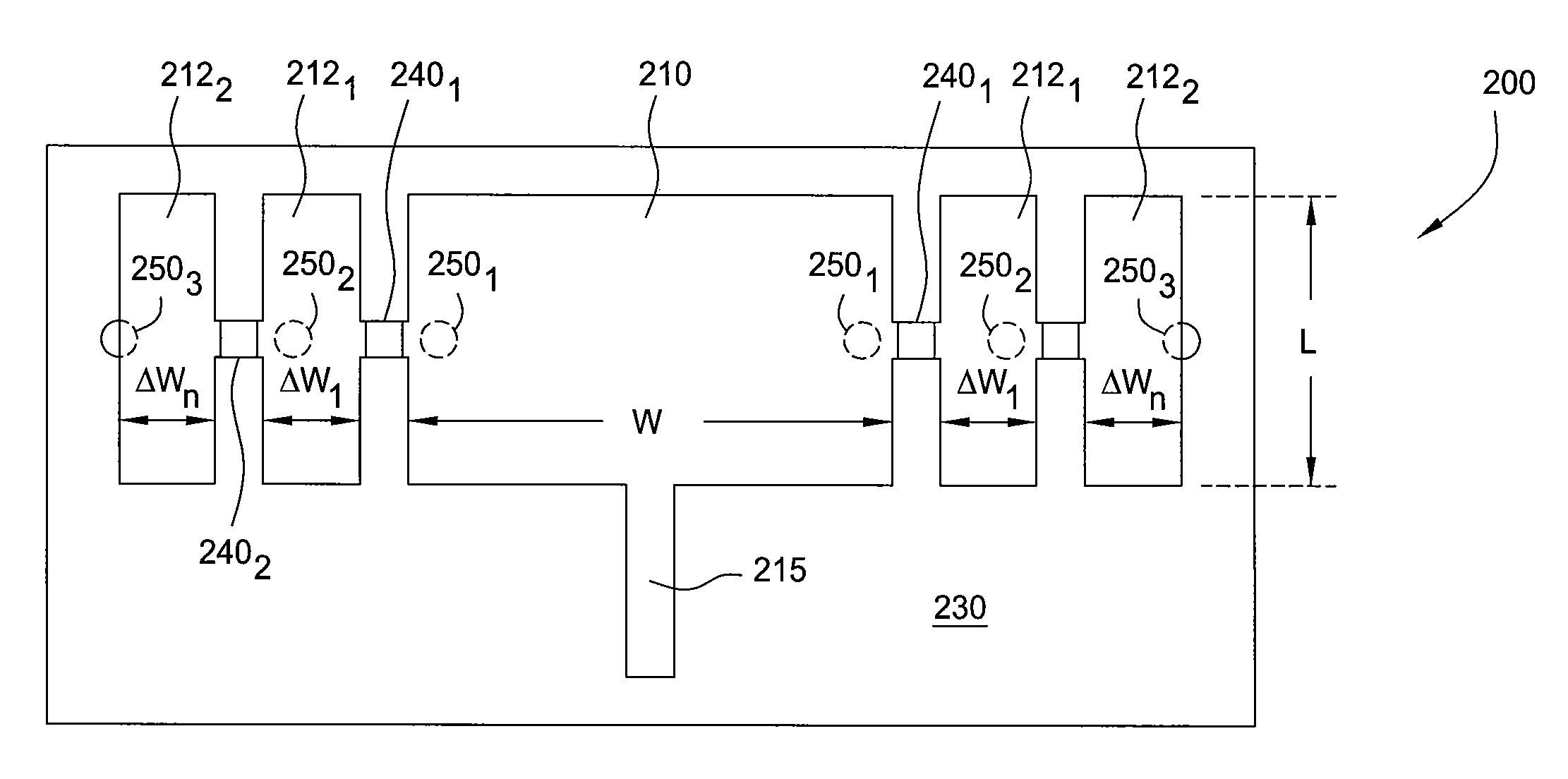
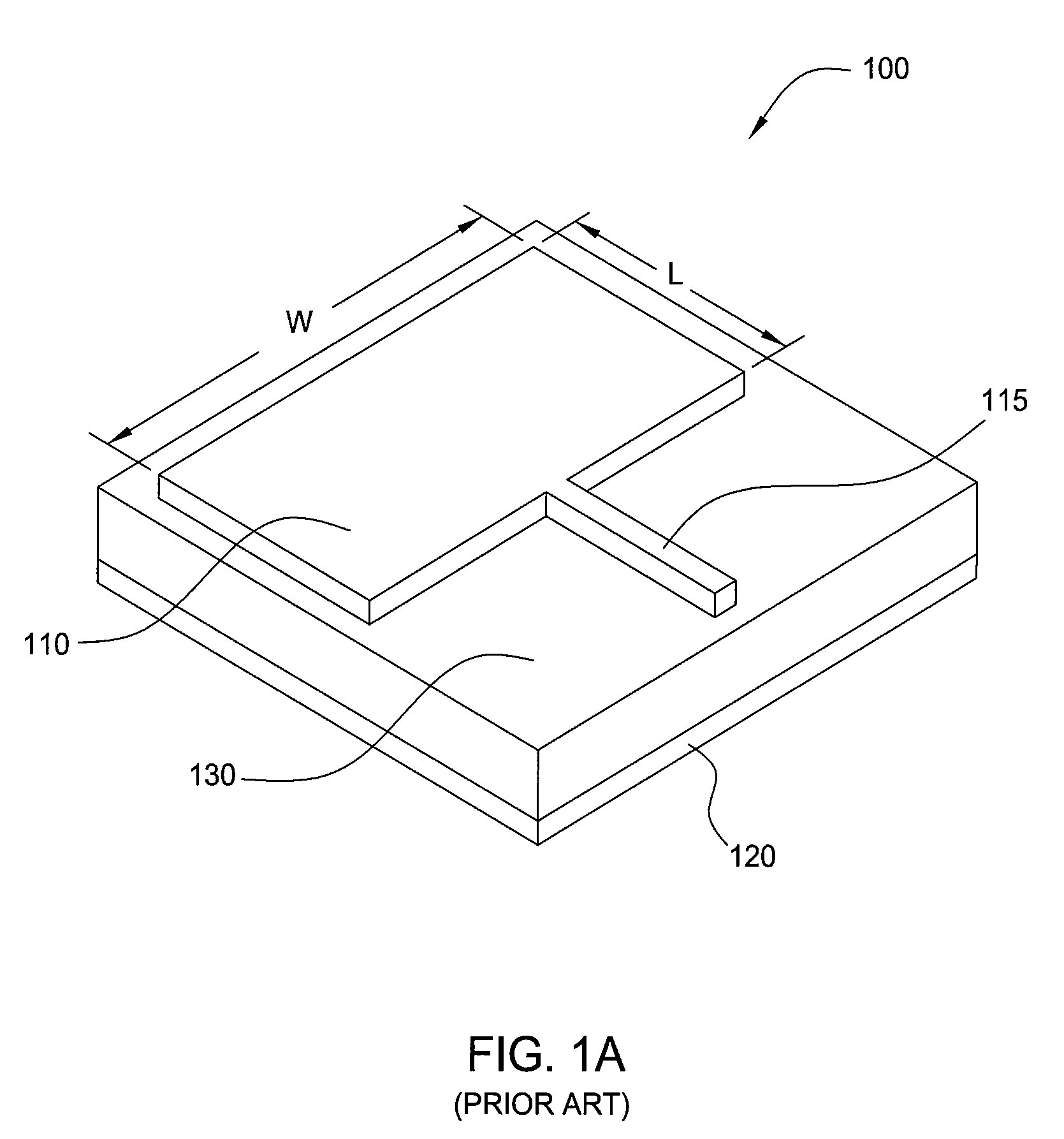
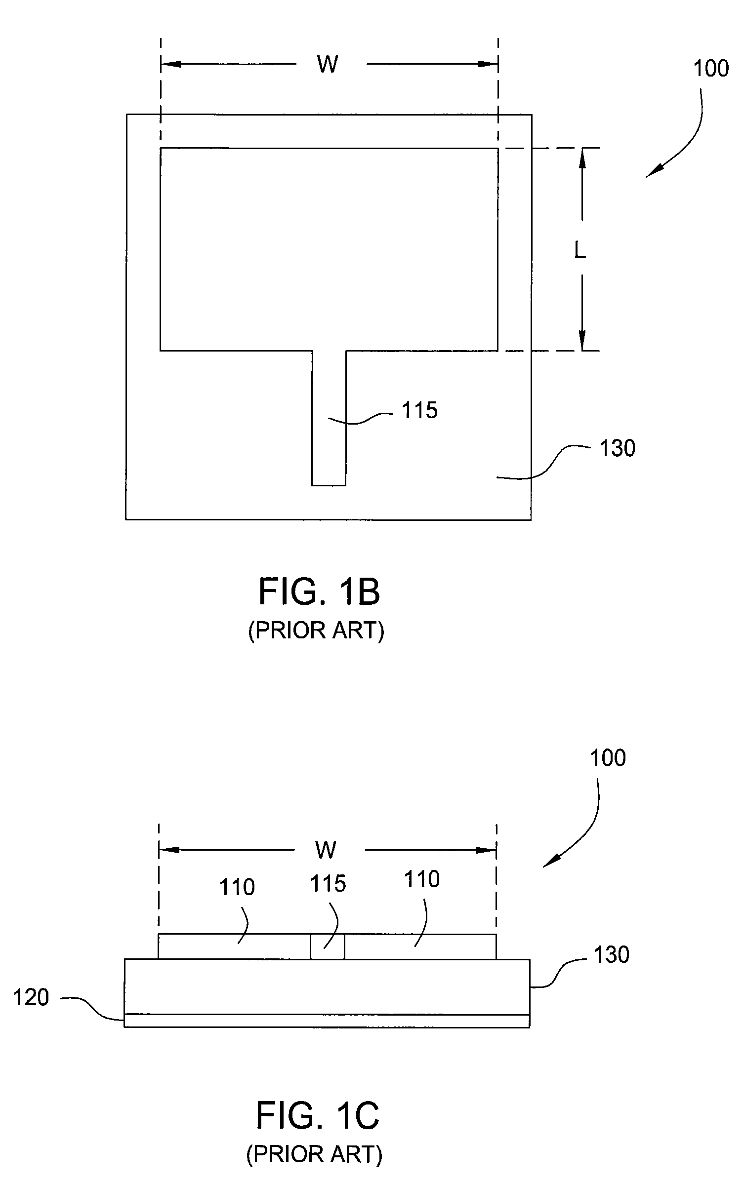
[0019]FIG. 1A depicts perspective view of an exemplary patch antenna 100 as presently known in the art. Patch antenna 100 is printed on one side of a microstrip substrate. It includes a radiating element 110 having a length ‘L’ and width ‘W,’ interacting with feed 115, disposed over a ground plane 120 and separated by a dielectric substrate 130. FIGS. 1B and 1C respectively display top and side views (on the feed side) of patch antenna 100 and its components (110, 115, 120 and 130). Various embodiments to be described will be discussed with respect to their top and side views, which may be compared to FIGS. 1B and 1C.

[0020]Patch antenna 100 is a rectangular design. However, it is known in the art that p...


PUM


Abstract

A method and apparatus providing a tunable channelized patch antenna by selectively adjoining one or more radiating element extensions successively to a radiating element of the patch antenna, and adjusting fringe capacitance at active outer edges of the patch antenna.

Description

FIELD OF THE INVENTION[0001]Various embodiments generally relate to wide band antennas and, more particularly, to tunable patch antennas.BACKGROUND OF THE INVENTION[0002]Patch antennas are known in the art. They typically comprise a metal sheet (patch) of specific dimensions with one or more carefully positioned feeds that is suspended over a ground plane. Patch antennas are generally small in size and utilized in higher frequencies (e.g., UHF and above), low profile applications. Such applications may include airborne and terrestrial vehicular applications, where form factor and aerodynamic drag of the antenna is a concern. Common applications of patch antennas in this regard are satellite radio antennas on an automobile or GPS antenna on an aircraft.[0003]Although patch antennas offer the above-mentioned benefits, the bandwidth of existing patch antennas is generally limited by the chosen dimensions of the patch. This makes many existing patch antenna designs inherently narrow ban...

Claims


Application Information

Patent Timeline
Patent Type & Authority Patents(United States)
IPC IPC(8): H01Q1/38
CPCH01Q9/0442
Inventor KANEDA, NORIAKIMETZ, CARSTEN
Owner ALCATEL-LUCENT USA INC
Why Eureka
Try Eureka