Diaphragm surrounding

a diaphragm and surrounding technology, applied in the direction of diaphragms of transducers, electrical transducers, instruments, etc., can solve problems such as buckling and affect acoustic performance, and achieve the effect of increasing the rocking stiffness of the apparatus

Active Publication Date: 2011-04-26
BOSE CORP
View PDF29 Cites 18 Cited by
  • Summary
  • Abstract
  • Description
  • Claims
  • Application Information

AI Technical Summary

Problems solved by technology

Geometric non linearities at high axial excursions in some surrounds can cause dynamic instabilities, parametric excitation of sub-harmonic rocking modes, and buckling that affects the acoustic performance.

Method used


Image

  • Diaphragm surrounding
  • Diaphragm surrounding
  • Diaphragm surrounding

Examples


Embodiment Construction

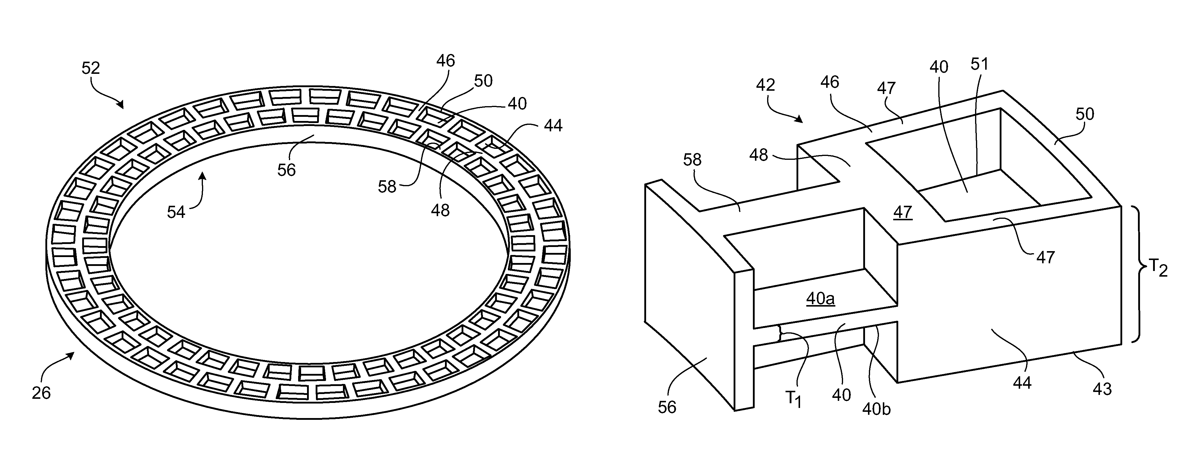
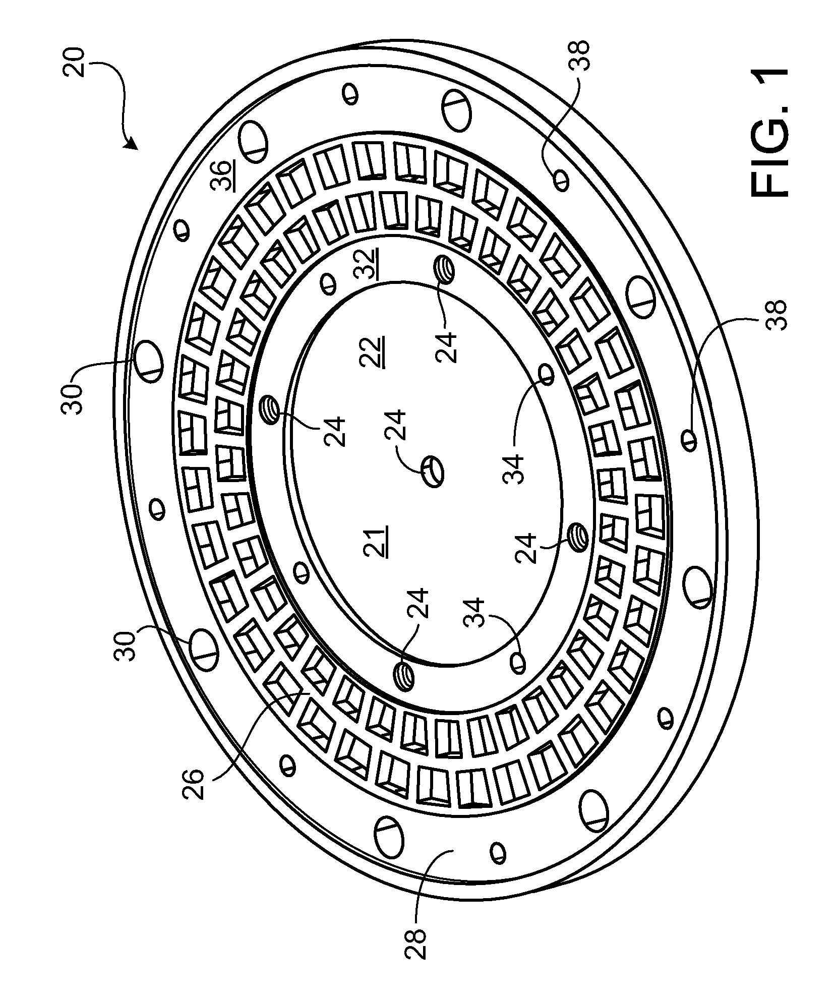
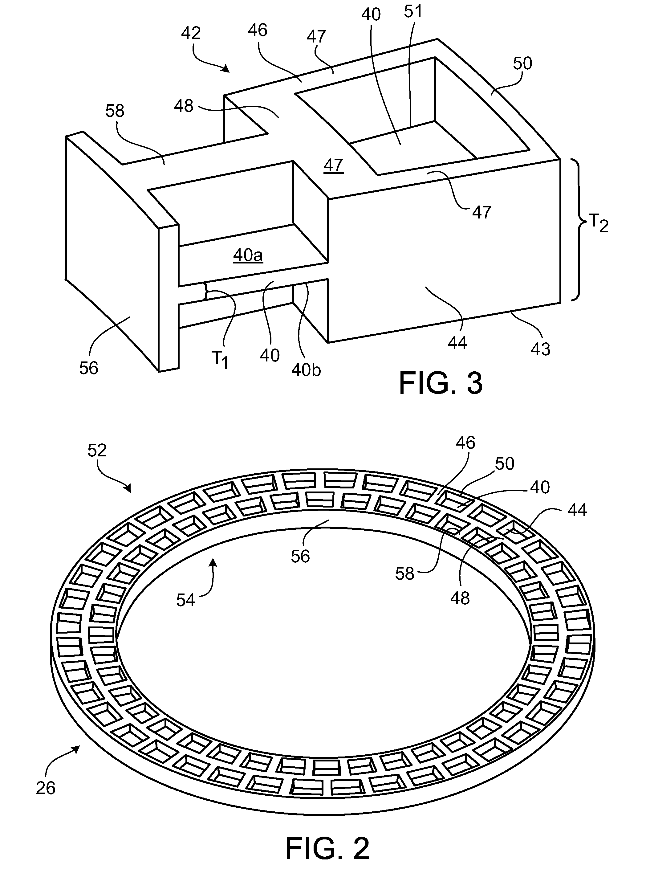
[0019]An active or passive acoustic source (e.g., a driver or a passive radiator) typically includes a diaphragm that reciprocates back and forth to produce acoustic waves. This diaphragm (which may be, e.g. a plate, cone, cup or dome) is usually attached to and supported by a non-moving structure through a resilient surround.

[0020]An example of a diaphragm and surround assembly 20 that achieves good performance (FIG. 1) includes a surround 26 that connects a diaphragm 22 to an outer attachment ring 36. In this example, the diaphragm 22 has a top surface 21 that is flat and made of a stiff material such as plastic (e.g., polycarbonate or Acrylonitrile Butadiene Styrene) or metal (e.g., steel or aluminum). In some examples, the top surface 21 of the diaphragm 22 may be convex or concave to make the diaphragm stiffer.

[0021]The diaphragm 22 is may be driven at its center 31 to produce acoustic waves by a source such as an electromagnetically driven acoustic driver (not shown). The acou...


PUM


Abstract

A surround for a diaphragm includes at least one rib section oriented to be extended during excursions of the diaphragm. The surround includes at least one membrane section supported by one or more rib sections contributing to a compliance characteristic different from the contribution of the one or more rib sections.

Description

CROSS-REFERENCE TO RELATED APPLICATION[0001]This application is a continuation-in-part of application Ser. No. 11 / 756,119, filed on May 31, 2007, entitled diaphragm surround.BACKGROUND OF THE INVENTION[0002]This invention relates to diaphragm surrounding.[0003]In traditional passive radiators and acoustic drivers, the surround that supports the diaphragm has a partially circular or elliptical cross-section and is made of a high durometer material to provide an approximately linear force-deflection response. Geometric non linearities at high axial excursions in some surrounds can cause dynamic instabilities, parametric excitation of sub-harmonic rocking modes, and buckling that affects the acoustic performance.BRIEF SUMMARY OF THE INVENTION[0004]According to the invention a surround for a diaphragm includes at least one rib section oriented to be extended during excursions of the diaphragm. There is at least one membrane section supported by the one or more rib sections with the one ...

Claims


Application Information

Patent Timeline
Patent Type & Authority Patents(United States)
IPC IPC(8): G10K13/00H04R7/20H04R7/18H04R7/16
CPCH04R7/20
Inventor SILVER, JASON D.
Owner BOSE CORP
Why Eureka
Try Eureka