
Audio jack with pogo pins for conductive contacts

a technology of pogo pins and conductive contacts, which is applied in the direction of coupling contact members, coupling device connections, instruments, etc., can solve the problems of large space occupation of cantilever beams within the audio jack assembly, and achieve the effect of preventing or reducing the chances of an audio jack snag

Active Publication Date: 2011-05-17
APPLE INC
View PDF6 Cites 46 Cited by
  • Summary
  • Abstract
  • Description
  • Claims
  • Application Information

AI Technical Summary

Benefits of technology

The patent describes an audio jack with pogo pins that make contact with the audio plug to transfer signals. The pogo pins are positioned in the audio jack and can be oriented in different ways to prevent snagging. The number and size of the pogo pins can be adjusted based on the size of the audio plug and the distance between the audio jack and the electronic device. The technical effect of this design is to provide a reliable and flexible connection between the audio plug and the electronic device, allowing for easy and secure signal transfer.

Problems solved by technology

The cantilever beam, however, can take up large amounts of space within the audio jack assembly.
This can especially be an issue for electronic devices so small that the audio jack size effectively determines the size of the device.

Method used


Image

  • Audio jack with pogo pins for conductive contacts
  • Audio jack with pogo pins for conductive contacts
  • Audio jack with pogo pins for conductive contacts

Examples


Embodiment Construction

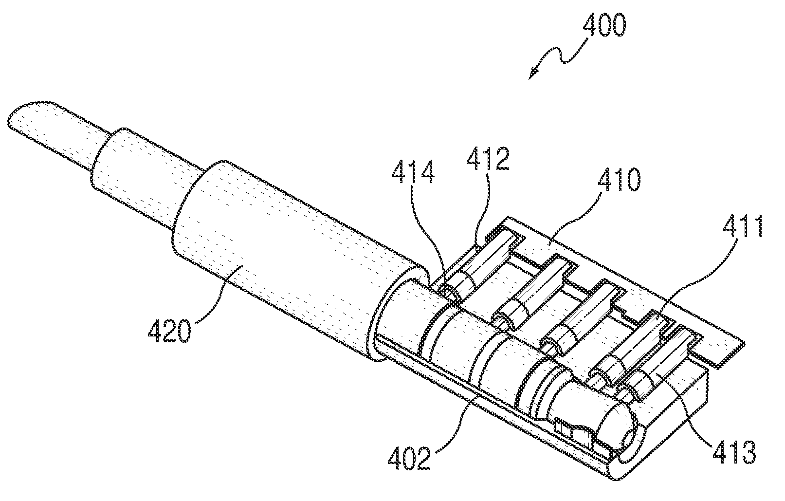
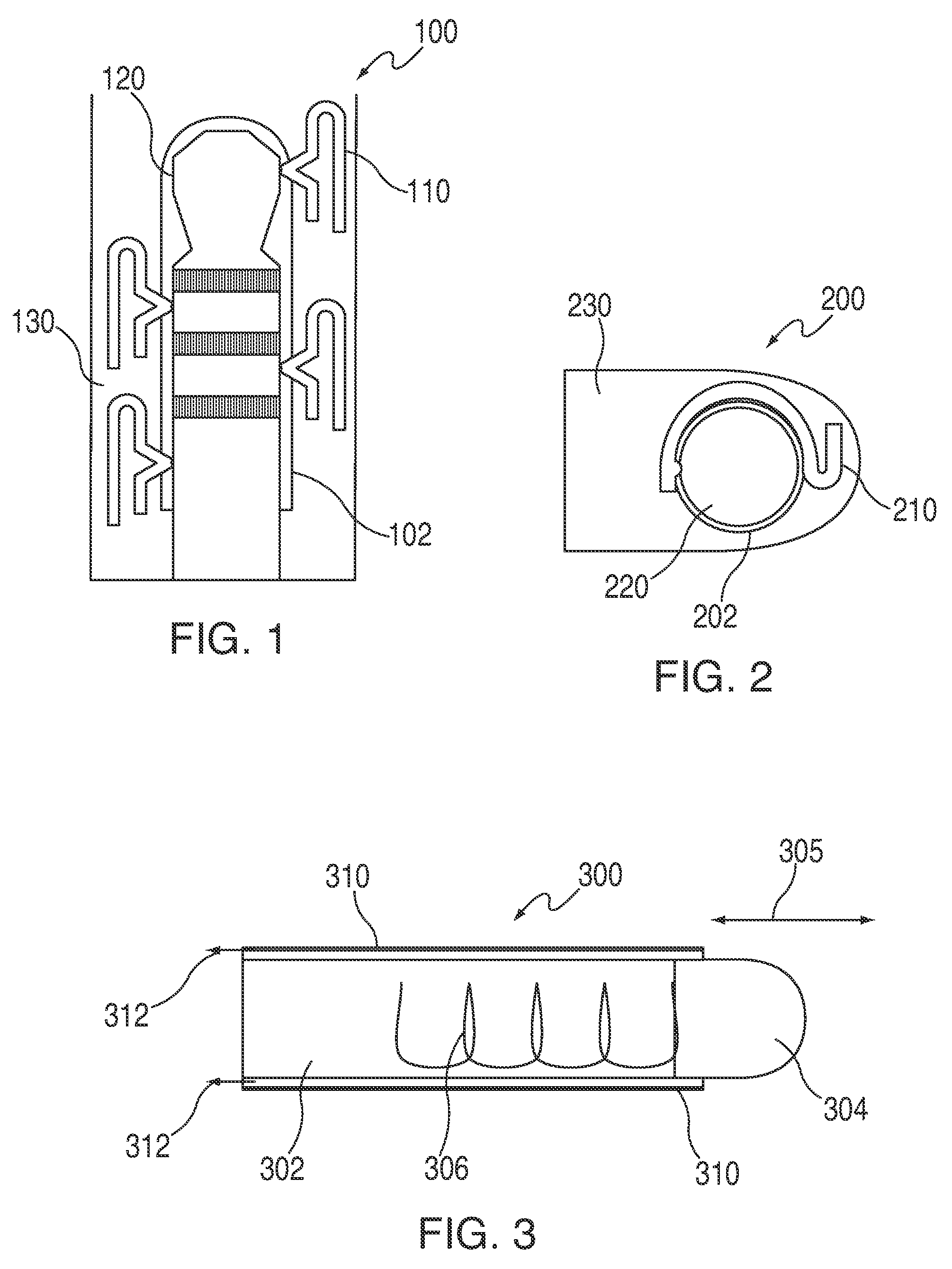
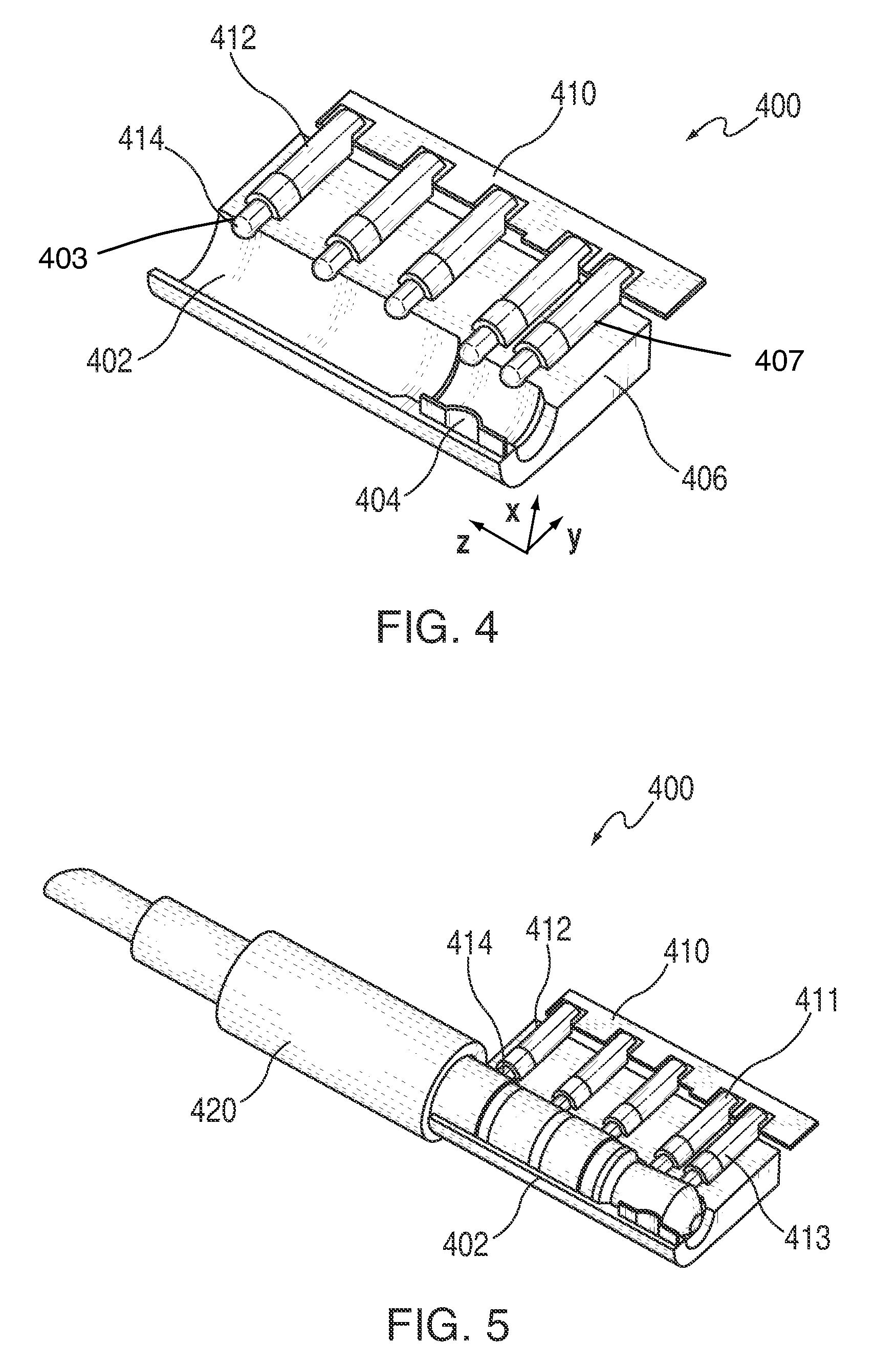
[0019]Embodiments of the following discussion will be described in the context of an audio jack. It will be understood, however, that features of the described embodiments can be applied to any suitable electronic connector, including for example an axial jack or connector (e.g., cylindrical axial jack for a cylindrical axial plug) for which pogo pins extend substantially orthogonal to the surface of the connector. Any suitable electronic or electrical plug can be placed within the electronic connector.

[0020]An audio jack can include several contact pads operative to electrically couple the conductive portions of an audio plug to electronic device components. The contact pads can take any suitable form. In some known embodiments, the contact pads can be constructed from pressed sheet metal and positioned such that they provide cantilever spring contacts for the audio plug. FIG. 1 is a schematic view of an illustrative audio jack and plug having stamped contact pads. Audio jack 100 c...


PUM

PropertyMeasurementUnit
angleaaaaaaaaaa
angleaaaaaaaaaa
angleaaaaaaaaaa

Abstract

An audio jack can allow electrical connections between an audio plug and an electronic device. The audio jack can include a series of pogo pins operative to extend into an audio jack cavity to provide conductive contacts for an audio plug placed within the audio jack. When an audio plug is inserted in the audio jack, the deflectable tips of each pogo pin can deflect and contact audio plug contact portions or regions. The end of the pogo pins opposite the deflectable tips can be coupled to an appropriate electronic device component, such as a printed circuit board, flex circuit, cable, or any other suitable component to provide a conductive path for signals between the audio plug and the electronic device.

Description

CROSS-REFERENCE TO RELATED APPLICATION[0001]This application claims priority to U.S. Provisional Application No. 61 / 162,210, filed Mar. 20, 2009, which is incorporated by reference herein in its entirety.BACKGROUND OF THE INVENTION[0002]This is directed to an audio jack using pogo pins to provide a low profile assembly.[0003]Many electronic devices include audio jacks for providing audio generated by electronic device circuitry to an audio output component coupled to the device. For example, many portable electronic devices include audio jacks to which headphone or speaker audio plugs can connect to transfer signals carrying the audio. Audio jacks include several conductive pads operative to contact audio plug contact portions or regions to provide electrical paths through which audio signals, power signals, and data signals can be transferred. The conductive pads typically can be formed from stamped sheet metal and can be shaped in a manner to ensure electrical contact and retentio...

Claims


Application Information

Patent Timeline
Patent Type & Authority Patents(United States)
CPCH01R13/2421H01R24/30H01R24/58Y10T29/49208H01R2107/00H04R2420/09H01R2105/00
Inventor MURPHY, SEANDIFONZO, JOHN
Owner APPLE INC
Learn More