
Bicycle trainer with variable magnetic resistance to pedaling

a bicycle trainer and variable technology, applied in the field of bicycle trainers, can solve the problems of limited options for user features such as seat style and tire size, no way to adjust front tire elevation or any adjustment of front and back translation of the bicycle, and each user has to adjust the settings

Active Publication Date: 2011-06-07
MANIAC HLDG LLC
View PDF43 Cites 18 Cited by
  • Summary
  • Abstract
  • Description
  • Claims
  • Application Information

AI Technical Summary

Benefits of technology

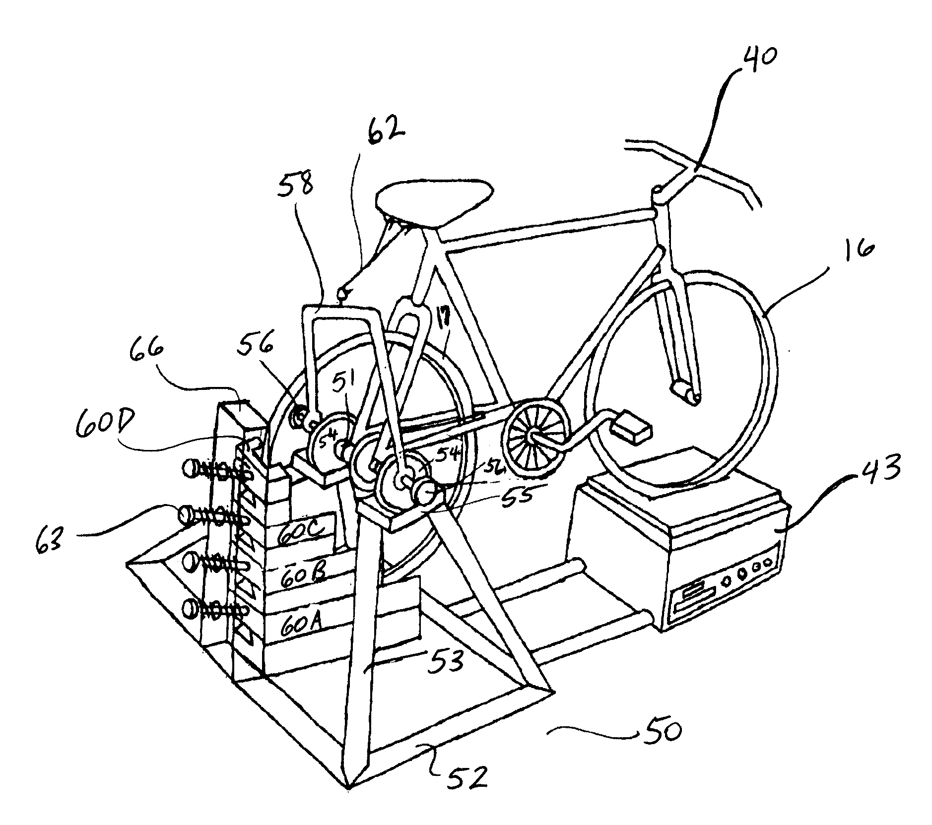
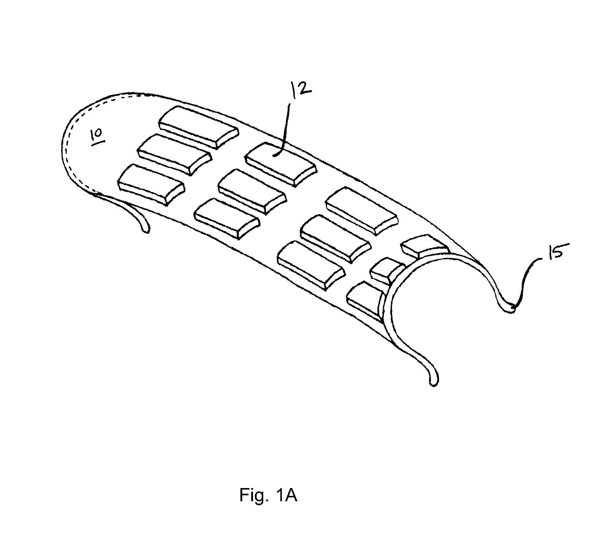
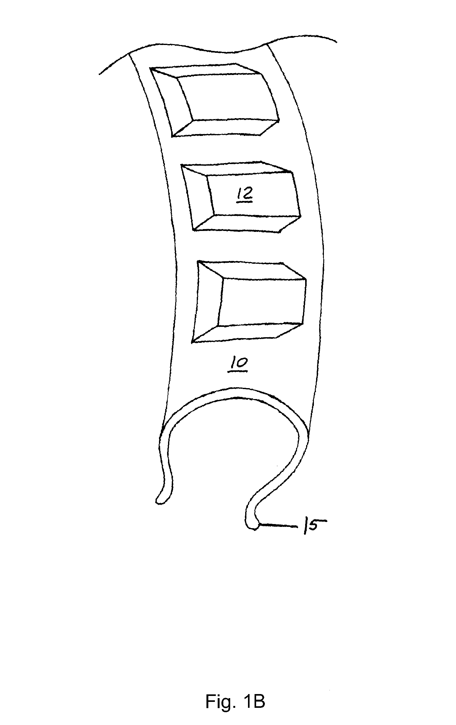
"The invention is a bicycle trainer that allows the rider to adjust the resistance to pedaling by using magnetic mechanisms on the rear wheel of the bicycle and a different magnetic mechanism. The first magnetic mechanism is part of the bicycle trainer and can be adjusted by the rider to change the magnetic field strength. The second magnetic mechanism is attached to the rear wheel of the bicycle and can also be adjusted to change the magnetic field strength. This allows the rider to adjust the resistance to rear tire revolution."

Problems solved by technology

One problem with stationary bicycles is that each user has to adjust the settings for their own preferences.
Additionally, the stationary bicycle must come in a one-size-fits-all version, meaning that the user has limited options in features such as seat style and tire size.
The Airmet '422 application, however, provides no way to adjust the front tire elevation or any adjustments to front and back translation of the bicycle.
While these documents show various combinations of front tire and rear tire lifts that a rider can use to maneuver a bicycle in a simulated training circuit, none of these embodiments provides for new ways of controlling the resistance element engaging the back tire.
Furthermore, none of these published patent applications provides for any forward and backward translation of the bicycle during times of raising and lowering the front tire.
Obviously, however, the stationary bicycle does not allow a user to exercise with his or her own standard bicycle that can be attached and detached to a portable trainer.

Method used


Image

  • Bicycle trainer with variable magnetic resistance to pedaling
  • Bicycle trainer with variable magnetic resistance to pedaling
  • Bicycle trainer with variable magnetic resistance to pedaling

Examples


Embodiment Construction

[0047]The invention encompasses a bicycle trainer that provides variable resistance to pedaling and allows for a rider to simulate a real-world bicycle course, including maneuvering up and down hilly terrain. Overall, the trainer 50 engages both the front tire 16 and the back tire 17 of the bicycle 40 and adjusts each according to the rider's preferences for training. One useful aspect of the disclosed trainer is its ability to accommodate an individual's personal bicycle 40. In other words, the trainer 50 does not include built-in biking equipment but lets a rider use his or her own bicycle 40 in a training situation. This distinguishes the trainer 50 from an exercise bicycle of the prior art.

[0048]The invention includes diverse mechanisms for controlling the resistance to pedaling that a user encounters when using the trainer 50. Each embodiment of the trainer includes parts and mechanisms that are interchangeable among each other. In other words, the invention is not limited to s...


PUM


Abstract

A bicycle trainer provides variable resistance to pedaling and allows for a rider to simulate a real-world bicycle course. The trainer engages both the front tire and the back tire of the bicycle and adjusts each according to the rider's preferences during a training session. The front tire lifts up and down as the bicycle moves forward and backward on the trainer. The back tire is adjusted by incorporating magnets thereon in the form of magnetic elements on a sleeve or a clip that engages the back tire and / or the back tire rim. The magnets on the back tire may also be attached to the spokes. The trainer includes magnets as well, usually of opposite polarity, and adds resistance to pedaling when the magnetic fields of the magnets interact to resist back tire revolution.

Description

CROSS-REFERENCE TO RELATED APPLICATIONS[0001]This application is a continuation-in-part and claims the benefit of priority to commonly owned U.S. patent application Ser. No. 12 / 206,696, entitled Bicycle Trainer with Variable Resistance to Pedaling, filed on Sep. 8, 2008 now U.S. Pat. No. 7,766,798. This prior application is incorporated by reference as if set forth fully herein.FIELD OF THE INVENTION[0002]The invention relates to the field of bicycle trainers for temporarily attaching a bicycle to a frame and for providing variable resistance to pedaling during a training session. The variable resistance is controlled by using magnetic fields between magnets on the rear bicycle wheel and magnets on the trainer.BACKGROUND OF THE INVENTION[0003]Bicycle trainers have been used in various forms for many decades. Early versions of stationary bicycles allowed a user to pedal on a stand for exercise. See U.S. Pat. No. 4,958,832 (Kim 1990). Over time, technology has progressed to a point wh...

Claims


Application Information

Patent Timeline
Patent Type & Authority Patents(United States)
IPC IPC(8): A63B69/16
CPCA63B24/0087A63B69/16A63B21/00069A63B21/0051A63B2220/78A63B2069/163A63B2069/165A63B21/00192A63B21/005A63B2069/164
Inventor HAMILTON, BRIAN H.
Owner MANIAC HLDG LLC
Learn More