Imaging apparatus

a technology of imaging apparatus and spherical tube, which is applied in the field of imaging apparatus, can solve problems such as complicated computation, and achieve the effects of uniform linear transformation or logarithmic transformation of electric signals, easy and quick correction of fluctuation, and suppression of conversion errors

Inactive Publication Date: 2011-06-07
KONICA MINOLTA INC
View PDF7 Cites 3 Cited by
  • Summary
  • Abstract
  • Description
  • Claims
  • Application Information

AI Technical Summary

Benefits of technology

[0064]According to the invention described in aspect 1, even if the input / output characteristics are subjected to fluctuation under the driving conditions, accurate linear transformation or logarithmic transformation of the electric signal can be uniformly provided by the characteristic conversion.
[0065]Further, easy and quick correction of fluctuation can be achieved, and the output signal near the switch point is corrected in conformity to the actual characteristics of the imaging element, using the model formulas of two characteristics on both sides of the switch point, whereby the conversion error can be suppressed, and the image quality can be improved.
[0066]The invention of aspect 2 provides the same advantages as those of the invention.
[0067]The invention of aspect 3 ensures accurate correction of the fluctuation in the input / output characteristics of the imaging element caused by the driving conditions.
[0068]The invention of aspect 4 ensures accurate correction of the fluctuation in the input / output characteristics of the imaging element caused by the driving conditions and pixel.
[0069]The invention of aspect 5 uses a lookup table to simplify the structure of the coefficient derivation section and to increase the derivation speed.

Problems solved by technology

The imaging element having a plurality of types of photoelectric conversion characteristics provides the output signal changed by a plurality of characteristics, and involves complicated computation in signal processing.

Method used


Image

  • Imaging apparatus
  • Imaging apparatus
  • Imaging apparatus

Examples


embodiment

[0126]Referring to drawings, the following describes the embodiments of the present invention:

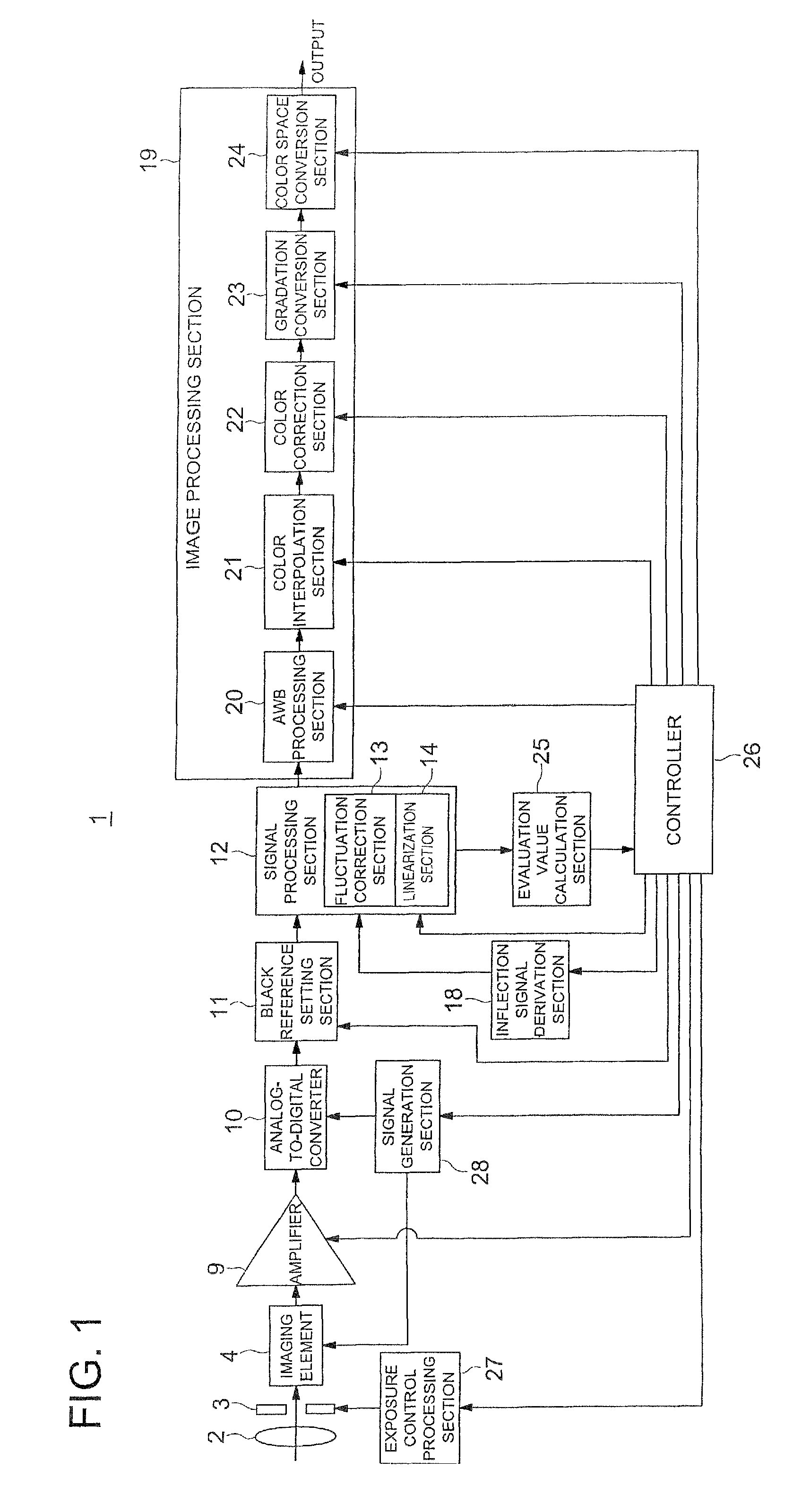
[0127]FIG. 1 is a block diagram representing the schematic structure of an imaging apparatus 1 of the present invention.

[0128]As shown in FIG. 1, the imaging apparatus 1 includes an imaging element 4 for receiving incident light through a lens group 2 and stop 3. The conventionally known lens group and stop can be used as the lens group 2 and stop 3.

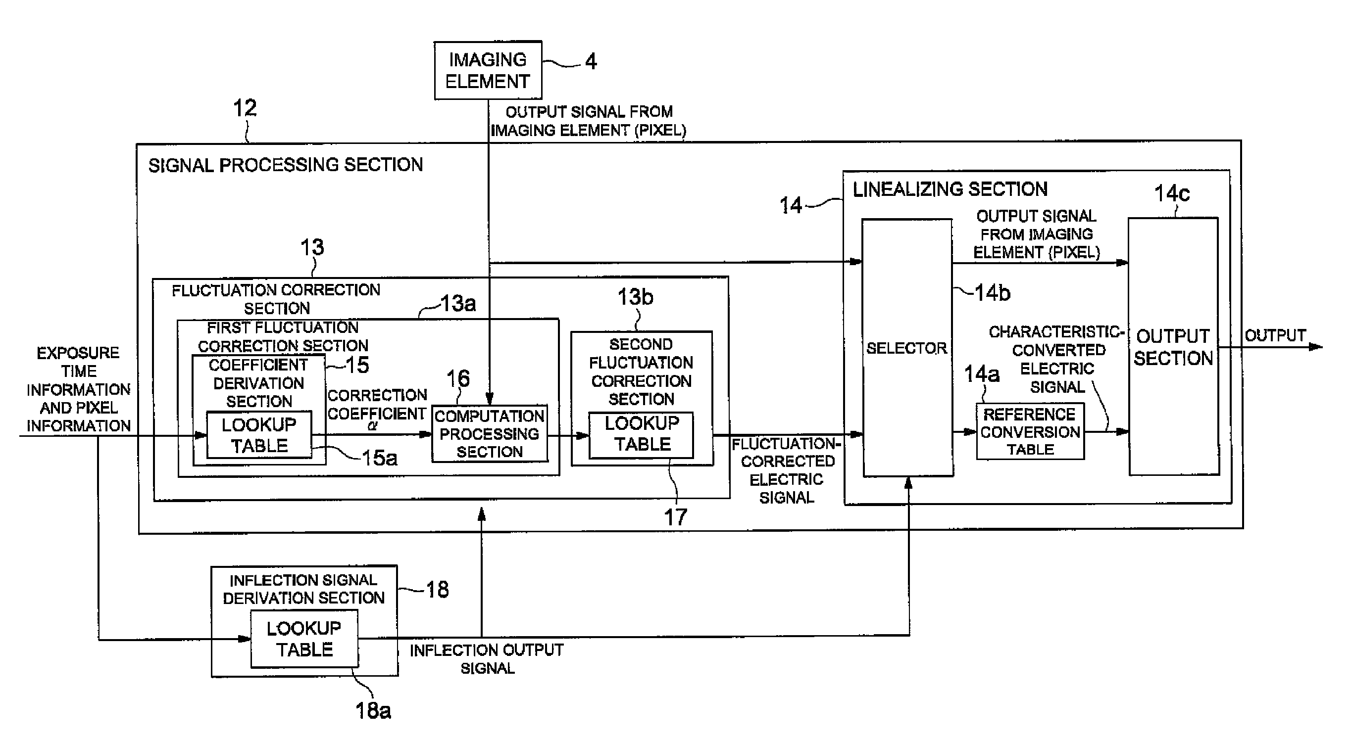
[0129]In this case, the imaging element of the present invention is an imaging element including a plurality of pixels that converts the incident light into electric signal using a plurality of types of conversion characteristics in such a way that the output signals having a plurality of types of conversion characteristics are changed on a continuous basis through the switch point.

[0130]The imaging element 4 of the embodiments is designed as a linear / log transformation sensor that switches between a linear transformation operation for linearly ...


PUM


Abstract

An imaging device (1) including; a fluctuation correcting section (13) for correcting fluctuation of the input / output characteristics of the imaging element (4), and the linearizing section (14) for converting the signals outputted from the imaging element (4) into the state where the output signals are uniformly converted by one conversion characteristic. The fluctuation correcting section (13) is provided with a first correcting section (13a) for correcting fluctuation based on a computing equation obtained by modeling a plurality of kinds of conversion characteristic, and a second correcting section (13b) for correcting the output signals in a region close to a switch point of a plurality of kinds of conversion characteristics among the output signals whose fluctuations are corrected by the first correcting section (13a), by using model equations of two characteristics on the sides of the switch point, so that the output signal overlaps the characteristic of the imaging element (4).

Description

[0001]This is a U.S. National Phase Application under 35 U.S.C. 371 of International Application PCT / JP2007 / 061362 filed on Jun. 5, 2007, which claims the priority of Japanese Application No. 2006-164651, filed Jun. 14, 2006, the entire content of both Applications are hereby incorporated by reference.FIELD OF THE INVENTION[0002]The present invention relates to an imaging apparatus provided with an imaging element for converting incident light into en electric signal.BACKGROUND OF THE INVENTION[0003]A conventional imaging apparatus such as a digital camera has been provided with an imaging element containing a plurality of pixels for converting incident light into an electric signal. One of the products proposed in recent years is an imaging element having a plurality of types of photoelectric conversion characteristics.[0004]One of the imaging elements having a plurality of types of photoelectric conversion characteristics is a linear / log transformation sensor that provides switchi...

Claims


Application Information

Patent Timeline
Patent Type & Authority Patents(United States)
IPC IPC(8): H04N5/228G06K9/40H04N5/235H01L27/00H04N5/335H04N5/355
CPCH04N5/335H04N5/35527H04N5/35518H04N25/573H04N25/575H04N25/00
Inventor TAKAYAMA, JUN
Owner KONICA MINOLTA INC
Why Eureka
Try Eureka