

Suspension display rack
a technology of suspension display rack and display rack, which is applied in the field of suspension display rack, can solve the problems of high material and manufacturing cost, inconvenient use, and incompatibility of the structure of the tool holder,
- Summary
- Abstract
- Description
- Claims
- Application Information
AI Technical Summary
Benefits of technology
Problems solved by technology
Method used
Image

Examples
Embodiment Construction
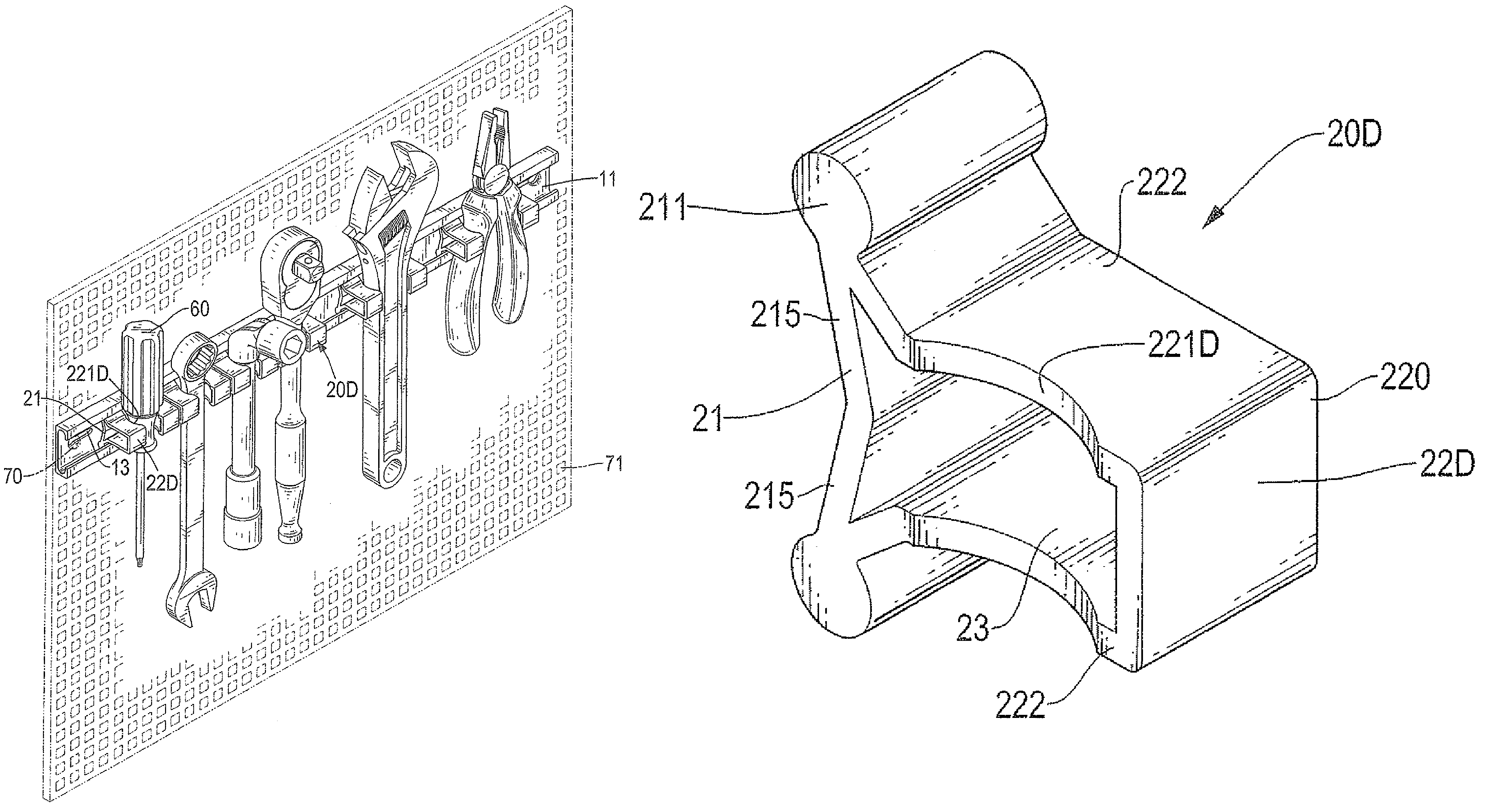
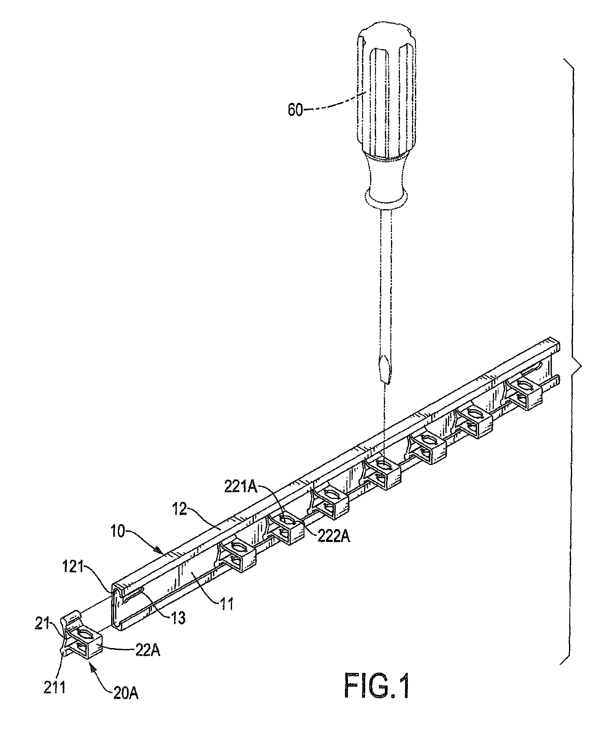
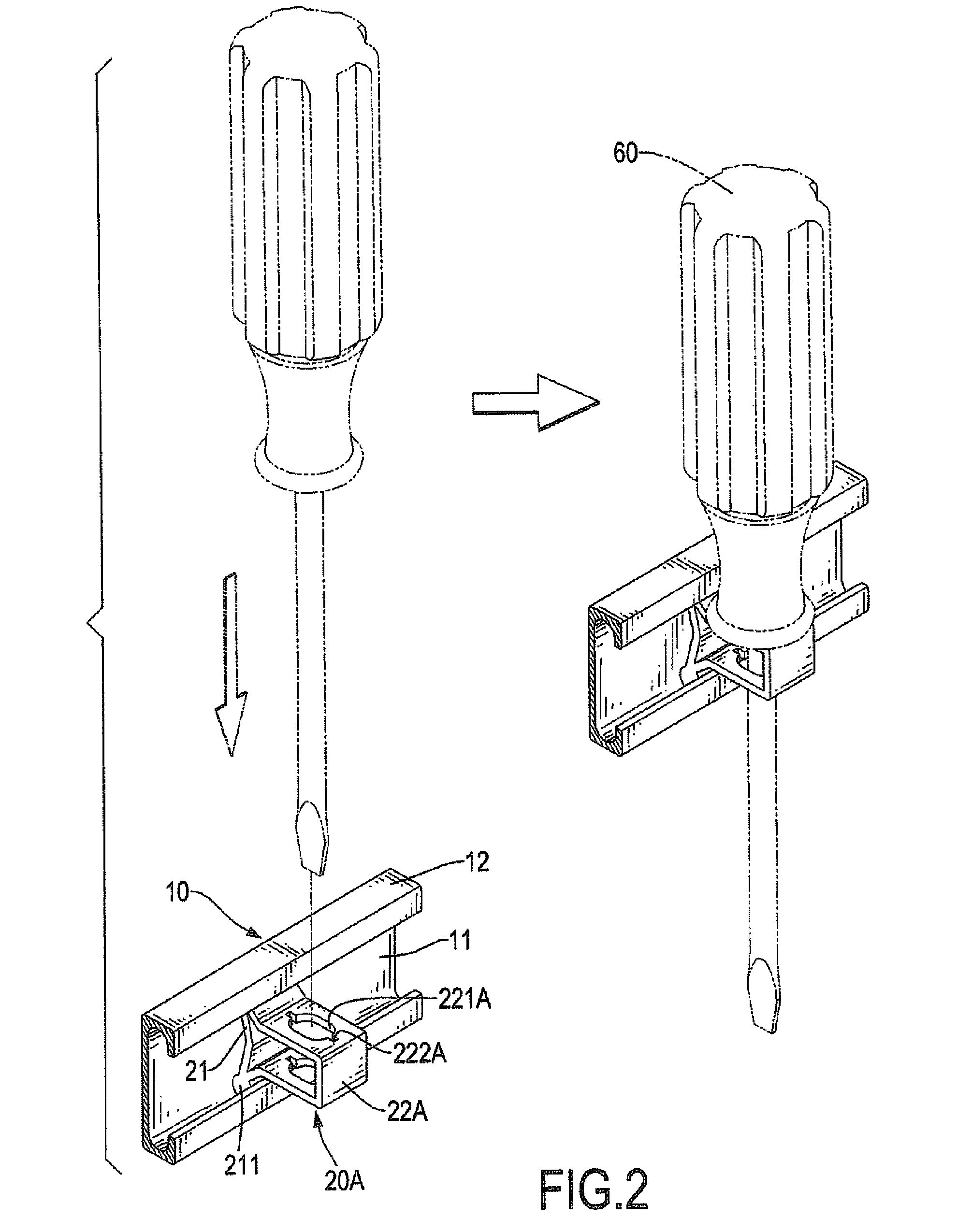
[0029]With reference to FIGS. 1-4, a first embodiment of a suspension display rack for hand tools in accordance with the present invention comprises a rail (10) and multiple sliding blocks (20A).
[0030]The rail (10) is longitudinal, may have a substantially C-shaped cross section and has back-strip (11) and two hooks (12) and two securing members (13).
[0031]The back strip (11) is longitudinal and flat and has an inner surface (111) a top edge, a bottom edge and two opposite ends. The inner surface (111) may be flat.
[0032]The hooks (12) are longitudinal, are formed on and perpendicularly protrude from the inner surface (111) respectively at the top and bottom edges of the back strip (11). The hooks (12) may be an upper hook and a lower hook being symmetrical to the upper hook formed in a same direction on the back-strip (11). Each hook (12) has a longitudinal groove (121). The longitudinal groove (121) is defined in the hook (12) at ajoint where the hooks (12) meet the back-strip (11)...
PUM
 Abstract
Description
Claims
Application Information