Re-circulating oven with gas clean-up

a gas clean-up and oven technology, applied in the field of ovens, can solve the problems of requiring frequent cleaning and a significant pressure drop across the catalyst, and achieve the effects of reducing the long-term stress on the oven components, and increasing the operating temperatur

Inactive Publication Date: 2011-08-30
TURBOCHEF TECH INC
View PDF130 Cites 111 Cited by
  • Summary
  • Abstract
  • Description
  • Claims
  • Application Information

AI Technical Summary

Benefits of technology

[0014]Accordingly, it is an object of the present invention to provide a cooking by-product control system for re-circulating ovens that eliminates the need for separate vent gas and main convection gas catalytic converters.
[0016]A further object is effective cooking by-product control at lower operating temperatures which allows for a more flexible cooking product (equipment) and reduces long term “stress” on the oven components resulting from higher operating temperatures.

Problems solved by technology

Controlling cooking by-products, such as grease, is challenging because in a speed cooking oven, for example, high velocity gas flow tends to entrain a great deal of grease, both particles and vapor, into the gas flow stream and untreated grease creates a number of issues including rapid soiling of the oven cavity surfaces and gas ducts, thereby requiring frequent cleaning; smoke, odor transfer between food products cooked either together in the cook chamber, or successively.
In such a system, all of the convection air passes through the main converter, thereby producing a significant pressure drop across the catalyst in the blower assisted convection loop.

Method used


Image

  • Re-circulating oven with gas clean-up
  • Re-circulating oven with gas clean-up
  • Re-circulating oven with gas clean-up

Examples


Embodiment Construction

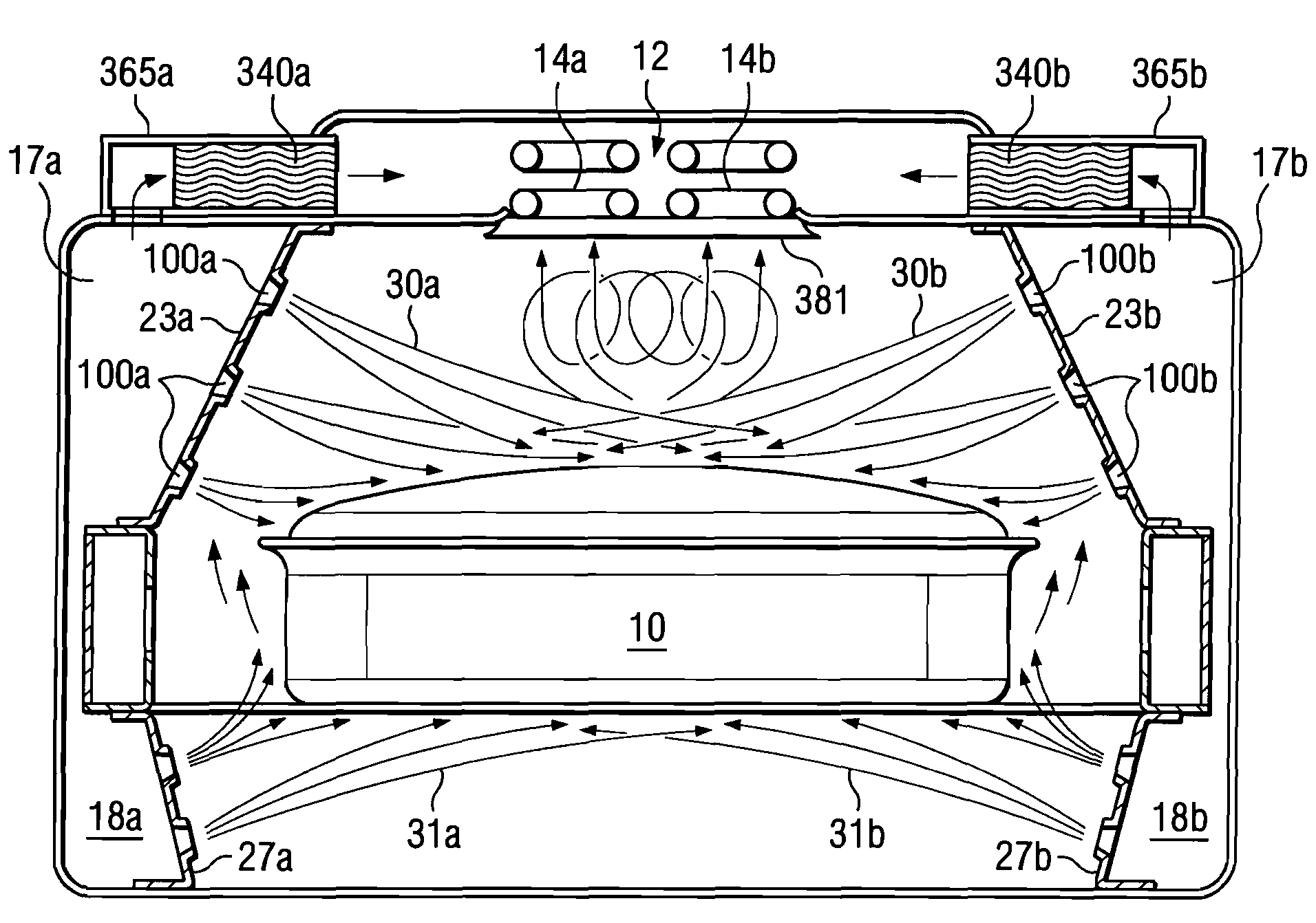
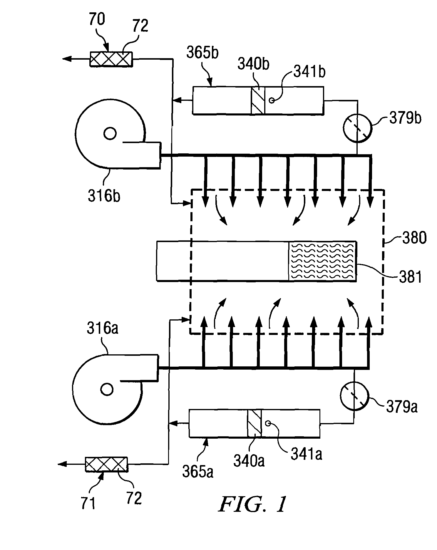
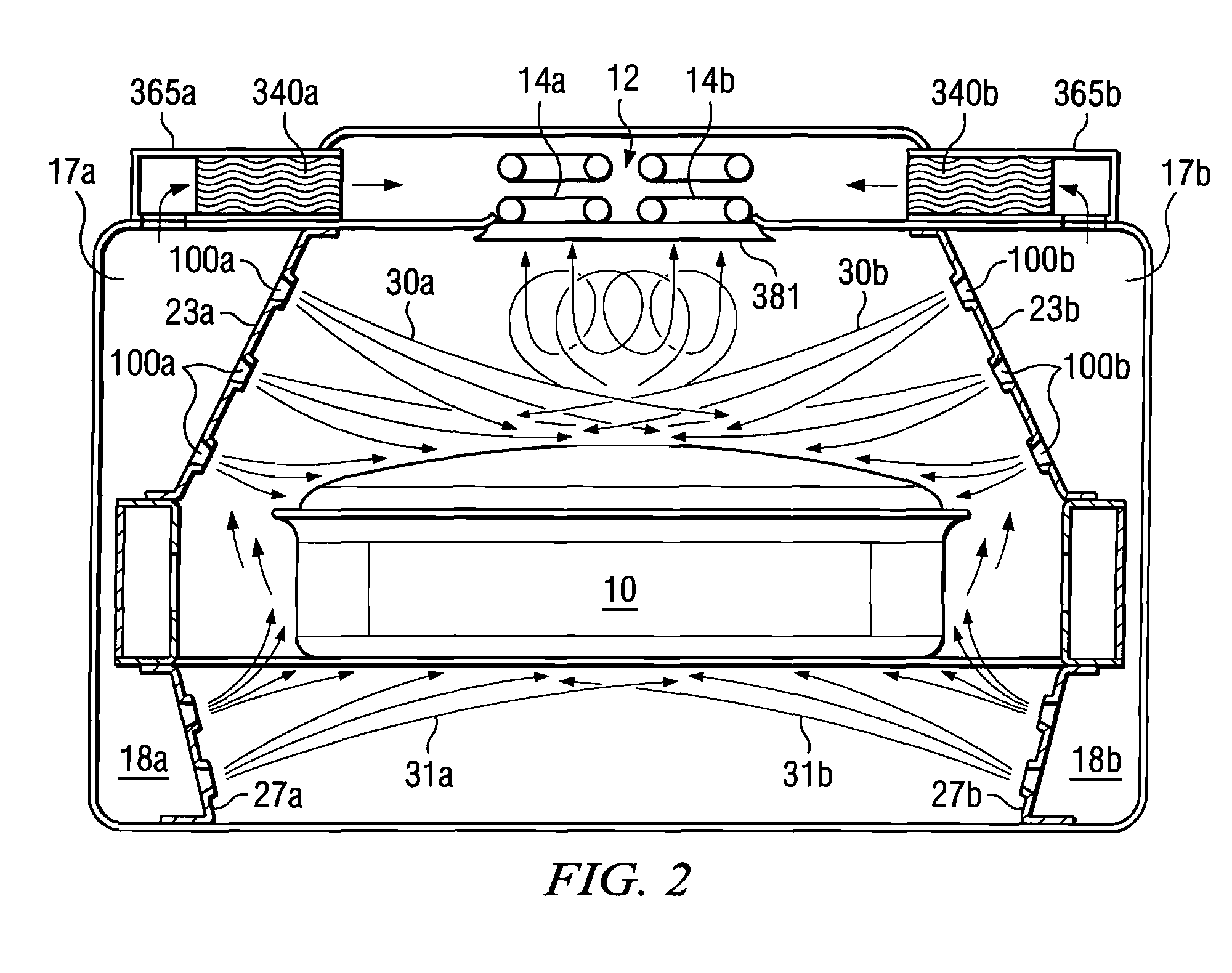
[0024]The exemplary embodiment is shown in conjunction with and utilized with a single cavity re-circulating speed cooking commercial oven, but the invention may be practiced with many other re-circulating oven embodiments and is not limited to the exemplary embodiment. The invention may also be scaled, either scaled up or scaled down. The term “scalable” and “scaled” herein means that additional larger or smaller versions may be developed, and each embodiment or version may have different size characteristics and utilize different cooking by-product destruction materials, cause various percentages of cooking by-product destruction and operate at various temperatures. Re-circulating gas flow within an oven has been described in commonly owned PCT Application Serial Number PCT / US2005 / 007261; U.S. Ser. No. 10 / 614,268, U.S. Ser. No. 10 / 614,479, U.S. Ser. No. 10 / 614,532, U.S. Ser. No. 10 / 614,710, U.S. Ser. No. 11 / 098,280 and U.S. Pat. No. 6,874,495 B2. Re-circulating gas flow may also b...


PUM


Abstract

A bleed gas clean-up system for a re-circulating oven.

Description

CROSS REFERENCE TO RELATED APPLICATIONS[0001]This application is the U.S. national phase of International Application No. PCT / US2005 / 035605 filed on Oct. 5, 2005 published in English on Apr. 20, 2006 as International Publication No. WO 2006 / 041814 A1, which application claims priority to U.S. Provisional Application No. 60 / 615,888 filed on Oct. 5, 2004; International Application No. PCT / US2005 / 007261 filed on Mar. 7, 2005; U.S. Provisional Application No. 60 / 661,591 filed on Mar. 14, 2005; and U.S. patent application Ser. No. 11 / 098,280 filed on Apr. 4, 2005, the contents of which are incorporated by reference herein.[0002]Upon entry into the National Stage in the United States of America, the present application will be a continuation-in-part of U.S. application Ser. No. 11 / 098,280 filed 4 Apr. 2005 now U.S. Pat. No. 7,360,533; will be a continuation-in-part of U.S. application Ser. No. 10 / 614,268 filed 7 Jul. 2003; will be a continuation-in-part of U.S. application Ser. No. 10 / 614...

Claims


Application Information

Patent Timeline
Patent Type & Authority Patents(United States)
IPC IPC(8): A47J37/00
CPCA21B1/245A47J37/0641
Inventor BOLTON, DAVID A.MCFADDEN, DAVID H.
Owner TURBOCHEF TECH INC
Why Eureka
Try Eureka