Check patentability & draft patents in minutes with Patsnap Eureka AI!

Retractable lens barrel with high shock resistance

a technology of shock resistance and lens barrel, which is applied in the direction of printers, instruments, cameras focusing arrangements, etc., can solve the problems of obstructed miniaturization of the lens barrel, and achieve the effect of improving the shock resistan

Inactive Publication Date: 2011-09-20
CANON KK
View PDF8 Cites 3 Cited by
  • Summary
  • Abstract
  • Description
  • Claims
  • Application Information

AI Technical Summary

Benefits of technology

This solution improves shock resistance and allows for the downsizing of digital cameras by reducing the length and diameter of the lens barrel while maintaining effective engagement and slip-off prevention, enhancing the barrel's resistance to external forces.

Problems solved by technology

For this reason, according to the technique described in Japanese Laid-Open Patent Publication (Kokai) No. 2005-128188, the movable cam ring is long in the direction of the optical axis, and this presents an obstacle in miniaturizing the lens barrel, and by extension an optical apparatus such as an image pickup apparatus having the lens barrel.

Method used


Image

  • Retractable lens barrel with high shock resistance
  • Retractable lens barrel with high shock resistance
  • Retractable lens barrel with high shock resistance

Examples


Embodiment Construction

[0020]The present invention will now be described in detail with reference to the drawings showing an embodiment thereof.

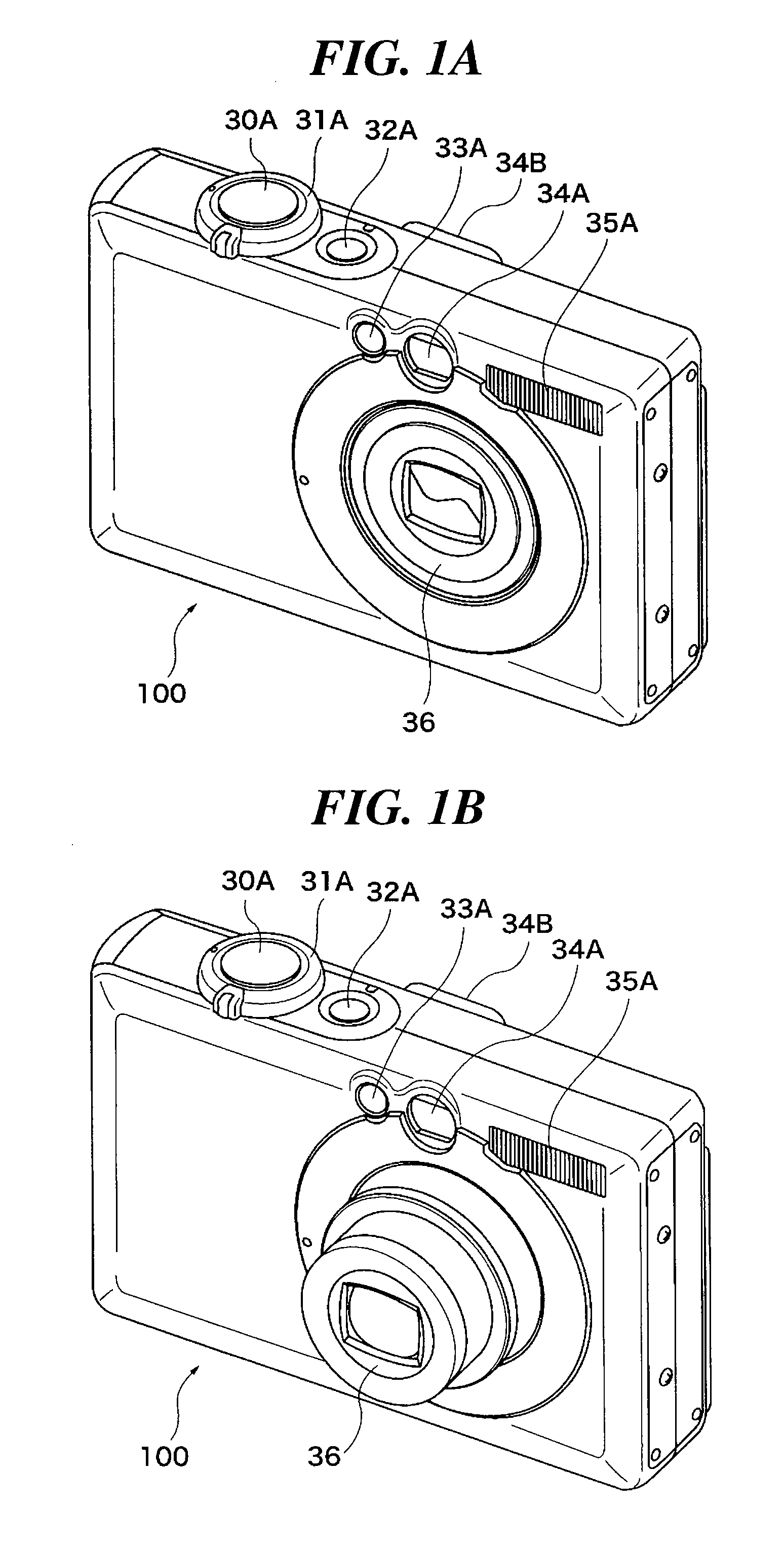
[0021]FIGS. 1A and 1B are external perspective views showing a digital camera having a retractable lens barrel according to an embodiment of the present invention, in which FIG. 1A shows a retracted state of the retractable lens barrel, and FIG. 1B shows an extended state of the retractable lens barrel.

[0022]Referring to FIGS. 1A and 1B, an auxiliary light window 33A, a finder window 34A, and a strobe light window 35A as well as the retractable lens barrel 36 are mounted in a front surface of the digital camera 100.

[0023]Auxiliary light is irradiated toward a subject from the auxiliary light window 33A at a time of photometric measurement and distance measurement. An optical image of a subject is taken into an interior of the camera from the finder window 34A, and the subject image can be viewed via a finder eyepiece 34B provided in a rear surface of the digital c...


PUM


Abstract

A retractable lens barrel that improves shock resistance without obstructing miniaturization. In the retractable lens barrel, pins formed in the lens barrel are engaged with grooves formed in a cam ring, and the lens barrel is caused to move in a direction of an optical axis by rotation of the cam ring. The pins include a cam pin for moving the lens barrel, and a slip-off preventive pin for preventing the cam pin from slipping off the groove. The grooves include a cam groove with which the cam pin is engaged, and a slip-off preventive groove with which the slip-off preventive pin is engaged. In an area close to a retracted position of the lens barrel, the cam groove and the slip-off preventive groove overlap to be shared grooves with which the cam pin and the slip-off preventive pin are engaged.

Description

BACKGROUND OF THE INVENTION[0001]1. Field of the Invention[0002]The present invention relates to a retractable lens barrel, and in particular to a zooming mechanism in which cam pins are engaged with cam grooves.[0003]2. Description of the Related Art[0004]Conventionally, optical apparatuses such as digital cameras having a zoom lens barrel of a retractable type (hereinafter referred to as a retractable lens barrel) have been in widespread use. As a zoom lens extension mechanism in a retractable lens barrel, there has been known a drive mechanism that engages cam pins formed in the lens barrel with cam grooves formed in a movable cam ring, and rotatively drives the movable cam ring to move the lens barrel forward and backward in a direction of an optical axis along the cam grooves. In such a zoom lens extension mechanism in which cam pins are engaged with cam grooves, it is necessary to prevent the cam pins from slipping off the cam grooves to render the lens barrel incapable of mov...

Claims


Application Information

Patent Timeline
Patent Type & Authority Patents(United States)
IPC IPC(8): G02B15/14G02B7/02
CPCG02B7/023G02B7/026G03B17/04G03B3/00G02B7/04
Inventor OYA, TAKAHIRO
Owner CANON KK
Features
  • R&D
  • Intellectual Property
  • Life Sciences
  • Materials
  • Tech Scout
  • Unparalleled Data Quality
  • Higher Quality Content
  • 60% Fewer Hallucinations
Learn More