Eureka AIR delivers breakthrough ideas for toughest innovation challenges, trusted by R&D personnel around the world.

Low flow showerhead and method of making same

a showerhead and low-flow technology, applied in the field of showerheads, can solve the problems of large water consumption, large pressure drop in the showerhead, and devices that fail to maintain sufficient pressure throughout the showerhead

Inactive Publication Date: 2011-10-04
WATER PIK INC
View PDF957 Cites 111 Cited by
  • Summary
  • Abstract
  • Description
  • Claims
  • Application Information

AI Technical Summary

Benefits of technology

[0008]Another embodiment of the present invention may take the form of a showerhead. The showerhead may include a showerhead engine and a flow control device. The showerhead engine may include at least two spray modes. The flow control device may be operatively associated with the showerhead engine. The flow control device may be selectively operable to pause fluid flow for any of the at least two spray modes. In some embodiments, the showerhead may further include a flow restrictor with a maximum flow rating of approximately 1.5 gallons per minute or less. The flow restrictor may be operatively associated with the showerhead engine and may limit a maximum fluid flow rate of a fluid delivered from the showerhead engine to approximately 1.5 gallons per minute.

Problems solved by technology

Unfortunately, a flow rate of 2.5 GPM still results in a large volume of water usage.
Showerheads may include a user selectable adjustment mechanism, for the adjustment of water pressure and / or spray pattern flowing from the showerhead, but such systems are dependent upon a user's selection and often positioned in a location of the hydraulic path leading to an unwanted pressure drop.
In addition, many such devices fail to maintain sufficient pressure throughout the showerhead, and in particular, often include flow patterns within the showerhead causing a large pressure drop in the showerhead before the water reaches the exit nozzles.
As a result, the showerhead does not work correctly, and discharges water at a low pressure, or with a weak spray, leading to an unsatisfactory shower experience.
This weak spray, on occasion, further causes users to remove the flow regulator to increase water flow and pressure, thereby eliminating any conservation advantages gained by the use of the flow regulator.

Method used


Image

  • Low flow showerhead and method of making same
  • Low flow showerhead and method of making same
  • Low flow showerhead and method of making same

Examples


Embodiment Construction

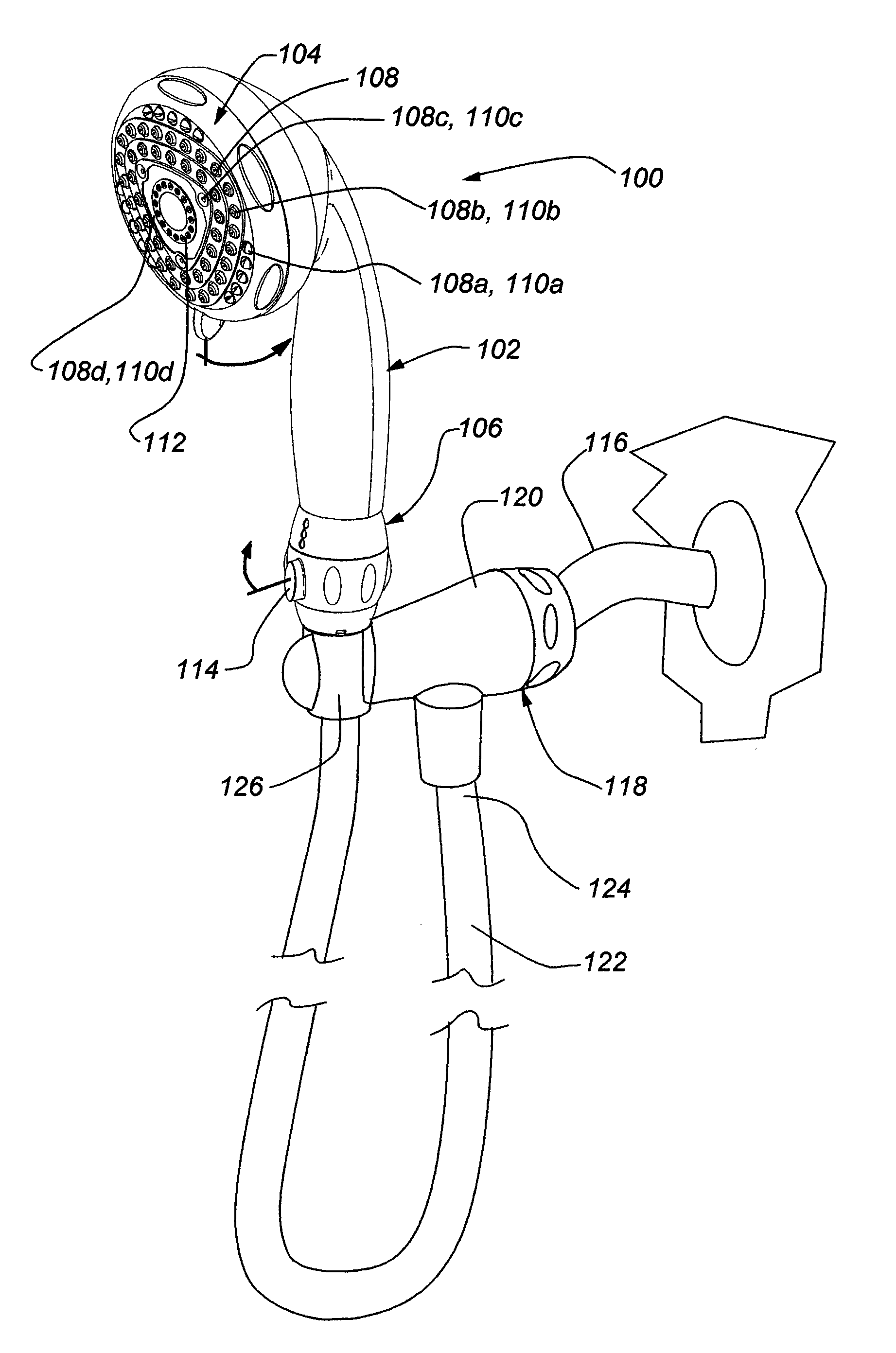
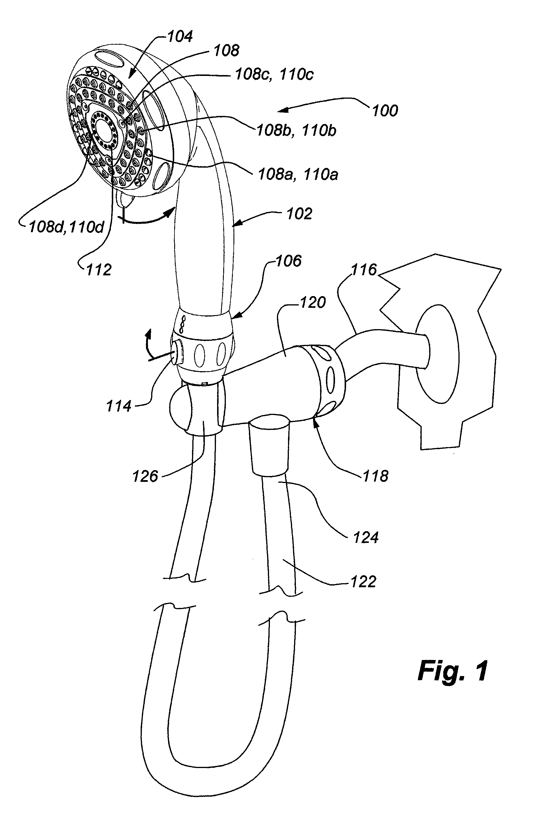
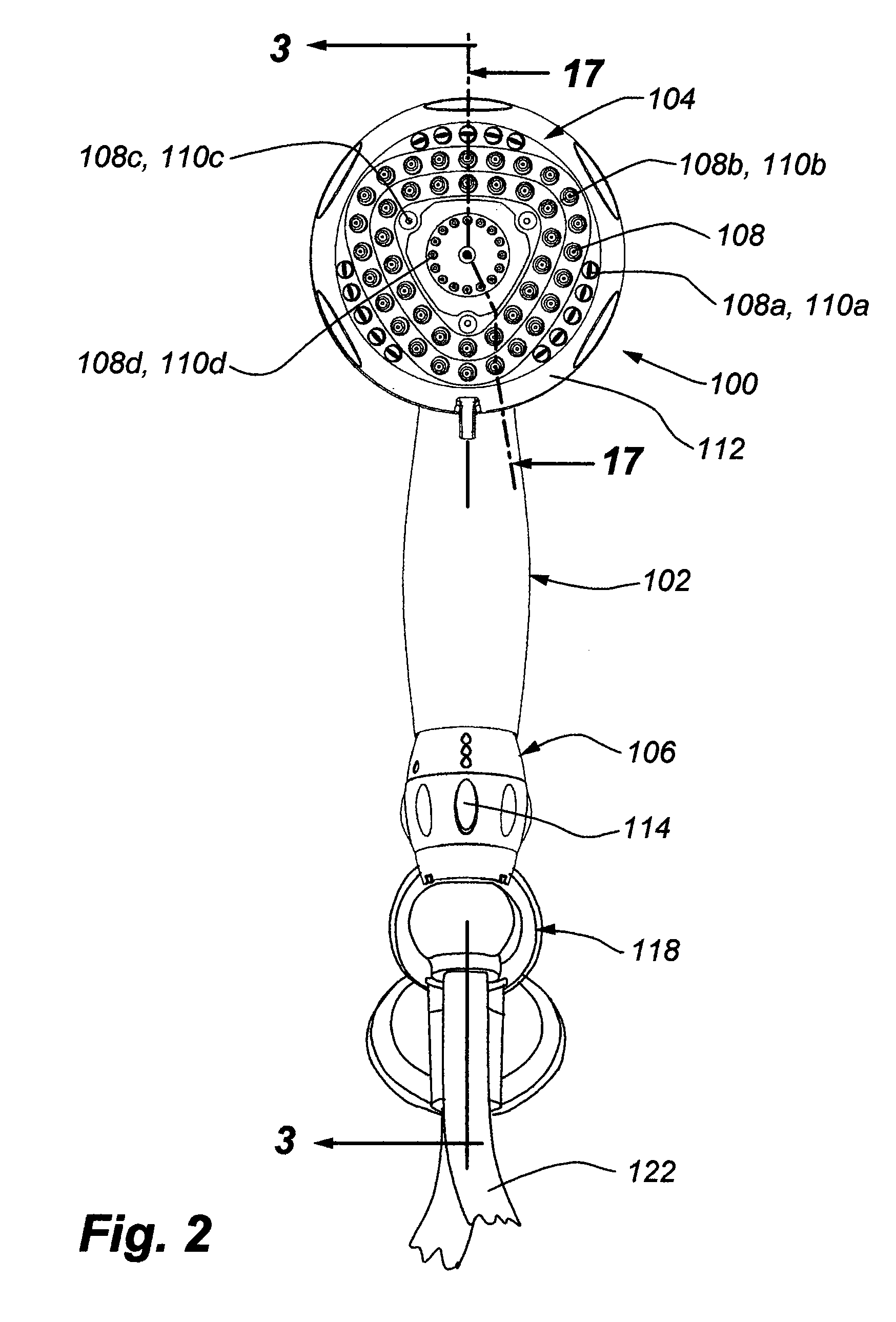
[0046]Described herein are various embodiments of showerheads and showerhead assemblies employing flow rates less than 2.5 gallons per minute (“GPM”). These showerheads and showerhead assemblies use flow regulators to supply flow rates less than the 2.5 GPM flow rate used in conventional showerhead. To accommodate these lower flow rates, the fluid passages within the showerhead and the fluid outlets that deliver fluid from the showerhead are configured and / or sized to increase fluid exit velocity compared to a conventional 2.5 GPM showerhead by minimizing fluid pressure drop or energy loss through the showerhead and / or by enhancing the pressure drop at the fluid outlet. The showerheads may further include large water passages to allow unrestricted flow to the exit nozzles, thus allowing the maximum available pressure drop at the fluid outlets to provide appropriate fluid exit velocities for the lower flow rate. Some embodiments of the showerhead may include a user operated flow devi...


PUM

PropertyMeasurementUnit
diameteraaaaaaaaaa
areaaaaaaaaaaa
circumferenceaaaaaaaaaa

Abstract

A showerhead for a low flow rate may employ one or more of a showerhead housing, a showerhead engine, a flow restrictor and a flow regulation device. The showerhead engine may be moveably connected to the showerhead housing. The showerhead engine may include a back member, an intermediate member, and a front member defining various fluid chambers and apertures that allow for one or more spray modes. The showerhead may include a flow control device to selectively reduce flow to the showerhead engine. The flow control device may also be selectively pause fluid flow for more than one spray mode. The showerhead may include a flow restrictor. The flow restrictor may limit a maximum fluid flow rate of a fluid delivered from the showerhead engine to approximately 1.5 gallons per minute.

Description

CROSS-REFERENCE TO RELATED APPLICATIONS[0001]This application claims under 35 U.S.C. §119(e) the benefit of U.S. provisional application No. 60 / 916,146, entitled “Low Flow Showerhead and Method of Making Same” and filed on May 4, 2007; U.S. provisional application No. 60 / 916,219, entitled “Hidden Pivot Attachment for Showers and Method of Making Same” and filed May 4, 2007; and U.S. provisional application No. 60 / 916,092, entitled “Molded Arm for Showerheads and Method of Making Same” and filed May 4, 2007, the disclosures of which are hereby incorporated herein by reference in their entireties.INCORPORATION BY REFERENCE[0002]The following patent applications are hereby incorporated by reference herein in their entireties: U.S. patent application Ser. No. 11 / 964,670, filed Dec. 26, 2007 and entitled “Low Speed Pulsating Showerhead”; U.S. patent application Ser. No. 12 / 112,697, filed Apr. 30, 2008 and entitled “Molded Arm for Showerheads And Method Of Making Same”; and U.S. patent ap...

Claims


Application Information

Patent Timeline
Patent Type & Authority Patents(United States)
IPC IPC(8): A62C31/00B05B15/68B29D99/00
CPCB29C66/126B29C65/562B05B15/067B29C65/56F16L27/047B05B15/065B29C66/54B29C65/561E03C1/021B29C65/00B29C65/08B29C69/004B29C66/1142B29C66/124Y10T29/49B29C65/48B29C66/55B29C65/58B05B1/18B29L2031/7696B29C65/02B29C41/04B05B15/654B05B15/65Y10T137/6858
Inventor LEBER, LELAND C.
Owner WATER PIK INC
Why Eureka
Eureka Blog
Learn More