
Electrical plug with a sliding cover extending from a front of an internal contact holder

Inactive Publication Date: 2011-10-11
KUO CHIE PRECISION INDAL
View PDF9 Cites 8 Cited by
  • Summary
  • Abstract
  • Description
  • Claims
  • Application Information

AI Technical Summary

Benefits of technology

[0007]The present invention has been accomplished under the circumstances in view. It is the main object of the present invention to provide an electrical plug carrying a fuse, which prohibits replacement of the fuse when the electrical plug is connected to an electrical outlet, keeping the fuse out of children's reach and avoiding accidental electric shock.
[0008]It is another object of the present invention to provide an electrical plug carrying a fuse, which prohibits entering of outside water to wet the internal metal conducting member set, avoiding short circuit or contact failure.

Problems solved by technology

1. No safety measure is provided: A cover is provided to protect the fuse and to keep the fuse from sight. If the fuse is burned out, the user can open the cover to replace the burnt fuse. However, there is no safety means to prohibit the cover from being opened when the electrical plug is connected to an electrical outlet. When replacing the fuse as the electrical plug is kept connected to the electrical outlet, an accidental electric shock may occur. Further, a child may open the cover and touch the internal circuit to cause an electric shock accidentally.
2. Component parts may be loosened easily: The component parts of conventional fuse-protected electrical plugs are assembled by means of electrically connecting the power cable to the metal conducting members and then installing the metal conducting members in an electrically insulative housing. When stretching the power cable, the metal conducting members may be biased, or the connection between the power cable and the metal conducting members may be loosened, resulting in an accidental shock circuit or occurrence of sparks or fire accident.

Method used


Image

  • Electrical plug with a sliding cover extending from a front of an internal contact holder
  • Electrical plug with a sliding cover extending from a front of an internal contact holder
  • Electrical plug with a sliding cover extending from a front of an internal contact holder

Examples


Embodiment Construction

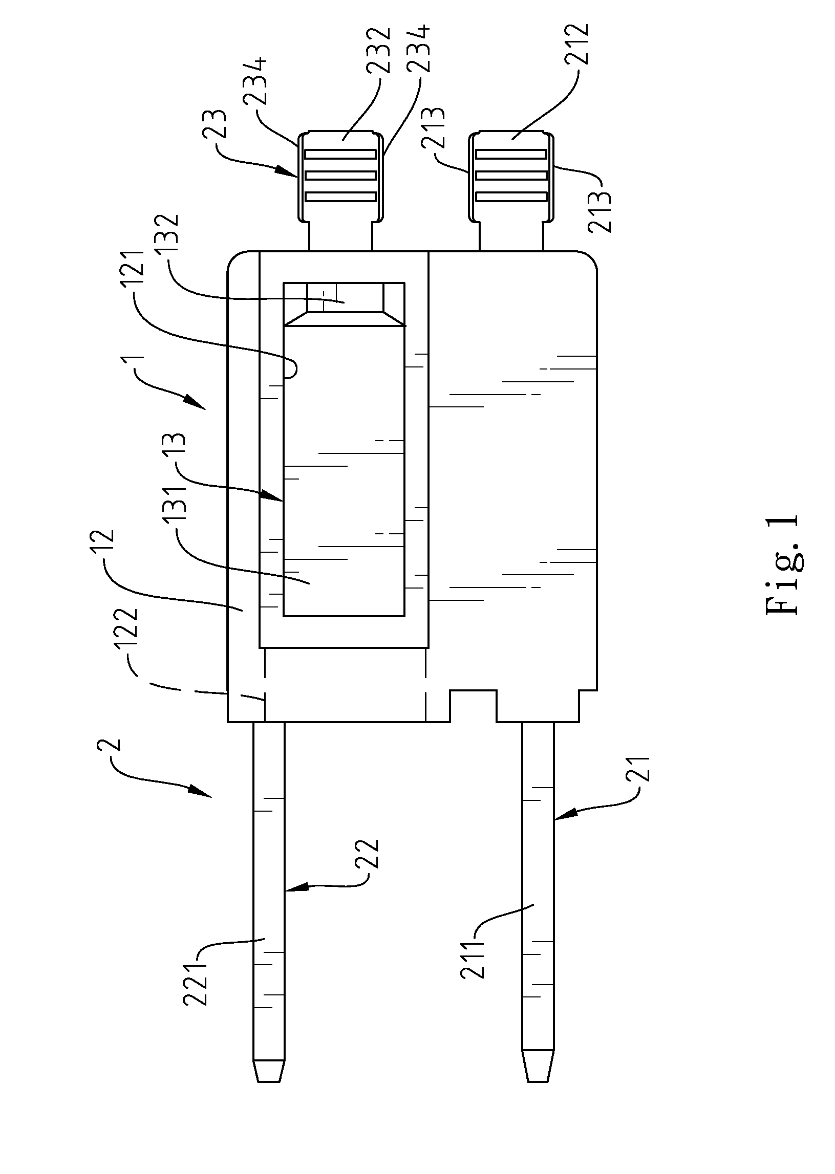
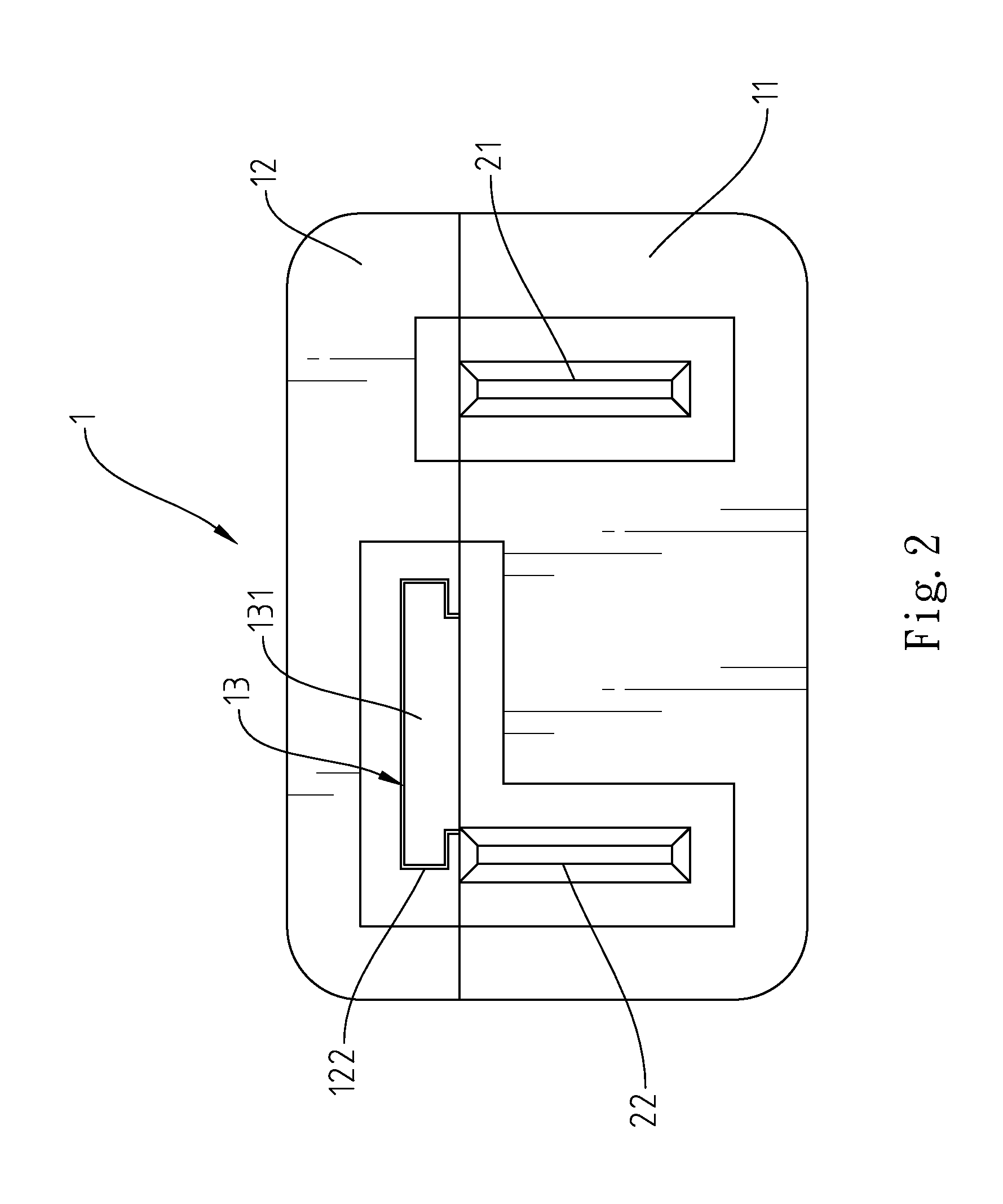
[0021]Referring to FIGS. 1-3, an electrical plug in accordance with a first embodiment of the present invention comprises an internal contact holder 1 and a metal conducting member set 2.

[0022]The internal contact holder 1 comprises a holder base 11, a top cover 12 covered on the holder base 11 and fixedly secured thereto by ultrasonic fusion, and a sliding cover 13 slidably mounted in the top cover 12. The top cover 12 has an opening 121 defined therein, and two sliding grooves 122 respectively located on two opposing inside walls thereof in the opening 121 and extending to the front side thereof. The sliding cover 13 comprises a cover body 131 coupled to the sliding grooves 122 and kept in close contact with the surface of the top cover 12 and movable along the sliding grooves 122 in and out of the top cover 12 to close or open the opening 121, and handle 132 perpendicularly upwardly extended from one end of the cover body 131 and suspending in the opening 121 to prohibit falling ...


PUM


Abstract

An electrical plug includes an internal contact holder, which comprises a holder base, a top cover covering the holder base and a sliding cover slidably coupled to two sliding grooves in an opening in the top cover and movable along the sliding grooves in and out of the top cover to close / open the opening, a first metal conducting member installed in the holder base and extending out of the front and rear sides of the holder base and a second and third metal conducting members installed in the holder base and respectively extended out of the front and rear sides of the holder base, and a fuse electrically connected between the second and third metal conducting members and suspending in the opening of the top cover.

Description

BACKGROUND OF THE INVENTION[0001]1. Field of the Invention[0002]The present invention relates to electrical plugs and more particularly, to an electric plug with a fuse therein, which keeps the fuse from sight and prohibits replacement of the fuse when the electrical plug is connected to an electrical outlet.[0003]2. Description of the Related Art[0004]Many electrical plugs are known having a fuse for current-limiting protection. However, these electrical plugs are still not satisfactory in function due to the following drawbacks:[0005]1. No safety measure is provided: A cover is provided to protect the fuse and to keep the fuse from sight. If the fuse is burned out, the user can open the cover to replace the burnt fuse. However, there is no safety means to prohibit the cover from being opened when the electrical plug is connected to an electrical outlet. When replacing the fuse as the electrical plug is kept connected to the electrical outlet, an accidental electric shock may occur...

Claims


Application Information

Patent Timeline
IPC IPC(8): H01R13/68
CPCH01R13/688H01R24/30H01R13/447H01R2103/00
Inventor CHO, I-CHIUNG
Owner KUO CHIE PRECISION INDAL
Learn More