
ECG electrode connector

a technology of ecg electrodes and connectors, which is applied in the direction of coupling device connections, diagnostic recording/measuring, applications, etc., can solve the problems of patient discomfort, patient discomfort, and patient discomfort, and achieve optimal electrical coupling

Active Publication Date: 2011-10-18
KPR U S LLC
View PDF4 Cites 26 Cited by
  • Summary
  • Abstract
  • Description
  • Claims
  • Application Information

AI Technical Summary

Benefits of technology

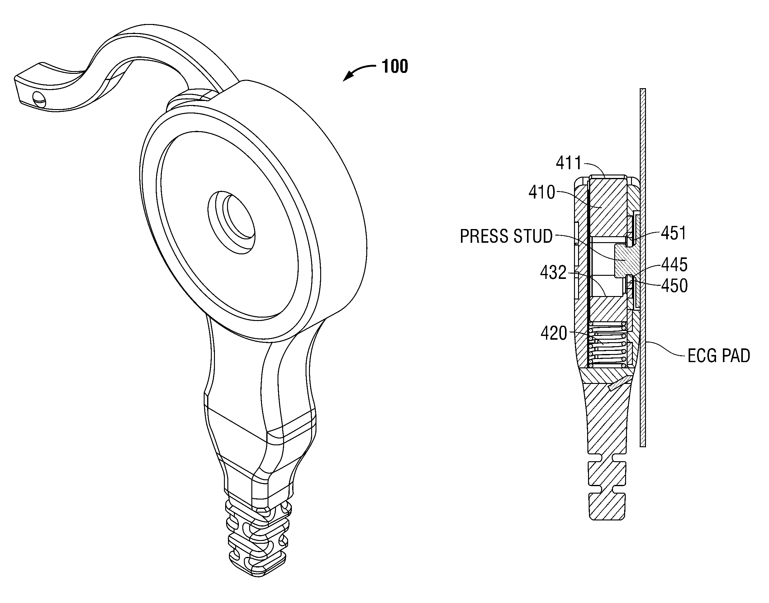
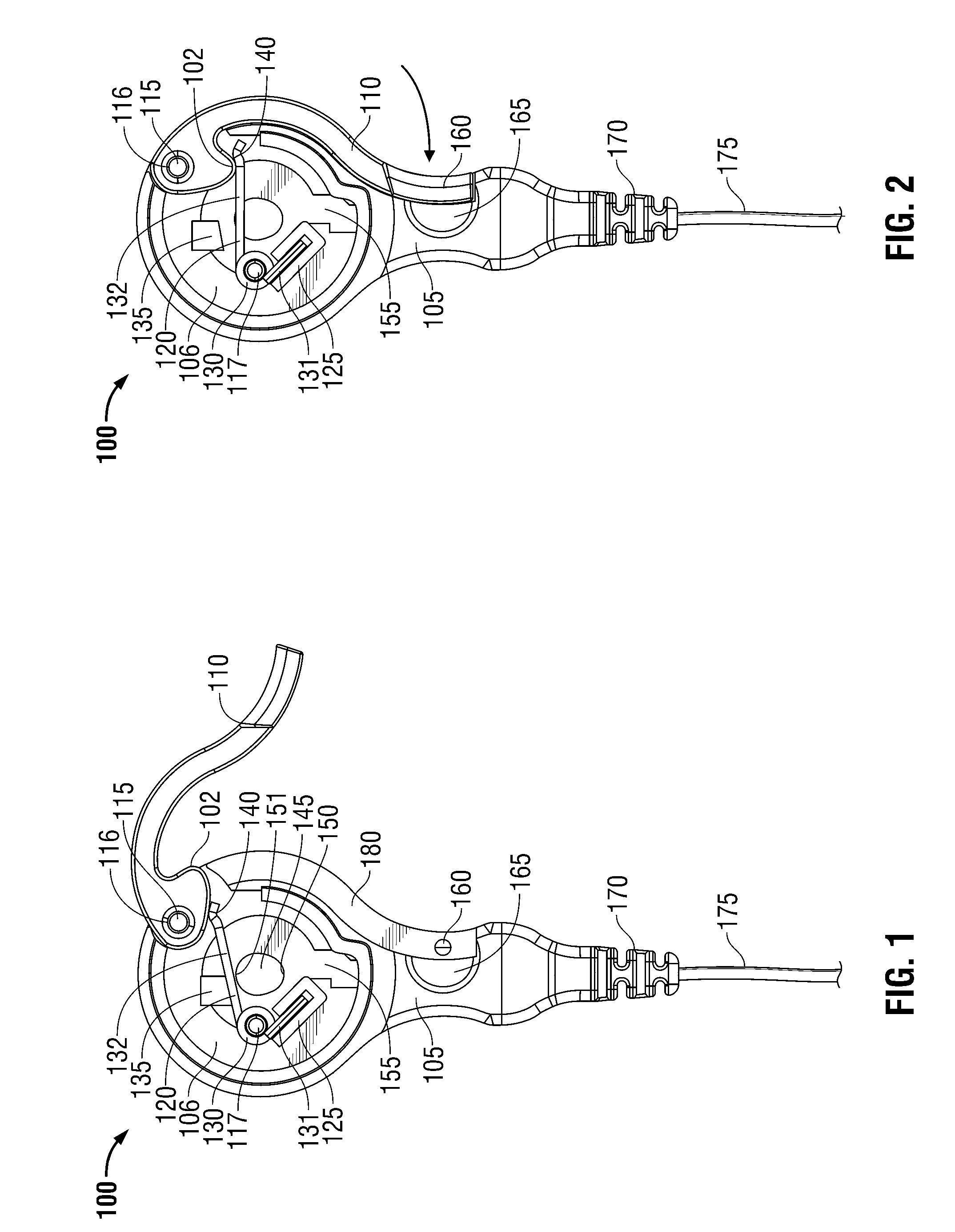
[0011]In an embodiment in accordance with the present disclosure, there is provided an ECG lead wire connector which includes a housing and a thumb cam lever having an open and a closed position. In the open position, the press stud of an ECG electrode assembly may be inserted into a mating receptacle provided in the housing, optionally using insignificant or no insertion force. Once placed in position, the thumb cam lever may be moved to the closed position, thereby positively coupling the press stud and connector without imparting undesirable force to the ECG electrode pad or to the patient. Detents may be provided by the disclosed lever to provide positive locking of the connector in the closed position to achieve optimal electrical coupling between the press stud and the connector, and additionally to provide tactile feedback to the clinician that the thumb cam lever is properly locked.
[0013]In another embodiment according to the present disclosure, an ECG lead wire connector is provided which includes a housing, and a pushbutton having an external face and an internal engaging surface. The pushbutton is biased by a spring member toward a locked position when released (i.e., when no pressure is applied to the pushbutton), and having an unlocked position when depressed (i.e., when sufficient pressure is applied to the face of the pushbutton by, for example, a clinician). A receptacle adapted to accept an electrode pad press stud is provided within the connector housing. When the pushbutton is depressed, the engaging surface thereof is configured to allow the insertion of a press stud into the receptacle, optionally using insignificant or no insertion force. Once the press stud is inserted, the pushbutton may be released, which causes the spring member to bias the engaging surface of the pushbutton against the press stud, engaging the press stud and a mating electrical contact member provided within the connector housing, to electrically couple the press stud and the contact member, and to achieve positive mechanical coupling of the press stud and the connector housing.

Problems solved by technology

This high connecting force may cause additional and unnecessary discomfort or pain to the patient, whose existing medical condition may already be a source of discomfort or pain.
A patient's discomfort may be compounded by the need to connect multiple electrodes which are customarily employed during ECG procedures.
Upon completion of the ECG procedure, a clinician must unsnap the ECG lead wire connector from the pad, which may further cause discomfort to the patient.
In some instances, the connector does not readily disengage from the press stud thus requiring the clinician to use considerable upward force to unseat the connector.
Often, these attempts to decouple the ECG lead wire connector from the electrode press stud will instead cause the pad to be suddenly and painfully torn from the patient's skin.
In other instances, attempts to detach the ECG lead wire will cause the pad to become partially dislodged from the patient, which may impair the electrode's ability to receive biopotential signals.
This is undesirable when, for example, the clinician wishes to detach the lead wires temporarily yet wishes to leave the pads in place to perform ECG testing on the patient at a future time.
In yet other instances, a snap lock connector may engage the press stud with insufficient force, which may cause suboptimal signal transmission from the electrode to the lead wire, as well as allowing the connector to be disengaged inadvertently by, for example, a slight tug on the lead wire.
These effects are undesirable, because they may invalidate the ECG procedure, requiring time-consuming re-testing of the patient, or may lead to delayed, inaccurate or unreliable test results.
Additionally, the process of snapping and unsnapping lead wire connectors from ECG pads, while simultaneously striving to avoid the above-mentioned adverse effects, requires considerable manual dexterity on the part of the ECG clinician.
Since clinicians typically repeat the electrode connection / disconnection routine many times each day, the described drawbacks may lead to clinician discontentment and fatigue.

Method used


Image

  • ECG electrode connector
  • ECG electrode connector
  • ECG electrode connector

Examples


Embodiment Construction

[0051]Embodiments of the presently disclosed ECG electrode connector and method are described herein in detail with reference to the drawings, in which like reference numerals designate identical or corresponding elements in each of the several views. As shown in the drawings and as described throughout the following description, and as is traditional when referring to relative positioning on an object, the term “proximal” refers to the end of the apparatus which is closer to the monitor and the term “distal” refers to the end of the apparatus which is further from the monitor. In the following description, well-known functions or constructions are not described in detail to avoid obscuring the present disclosure in unnecessary detail.

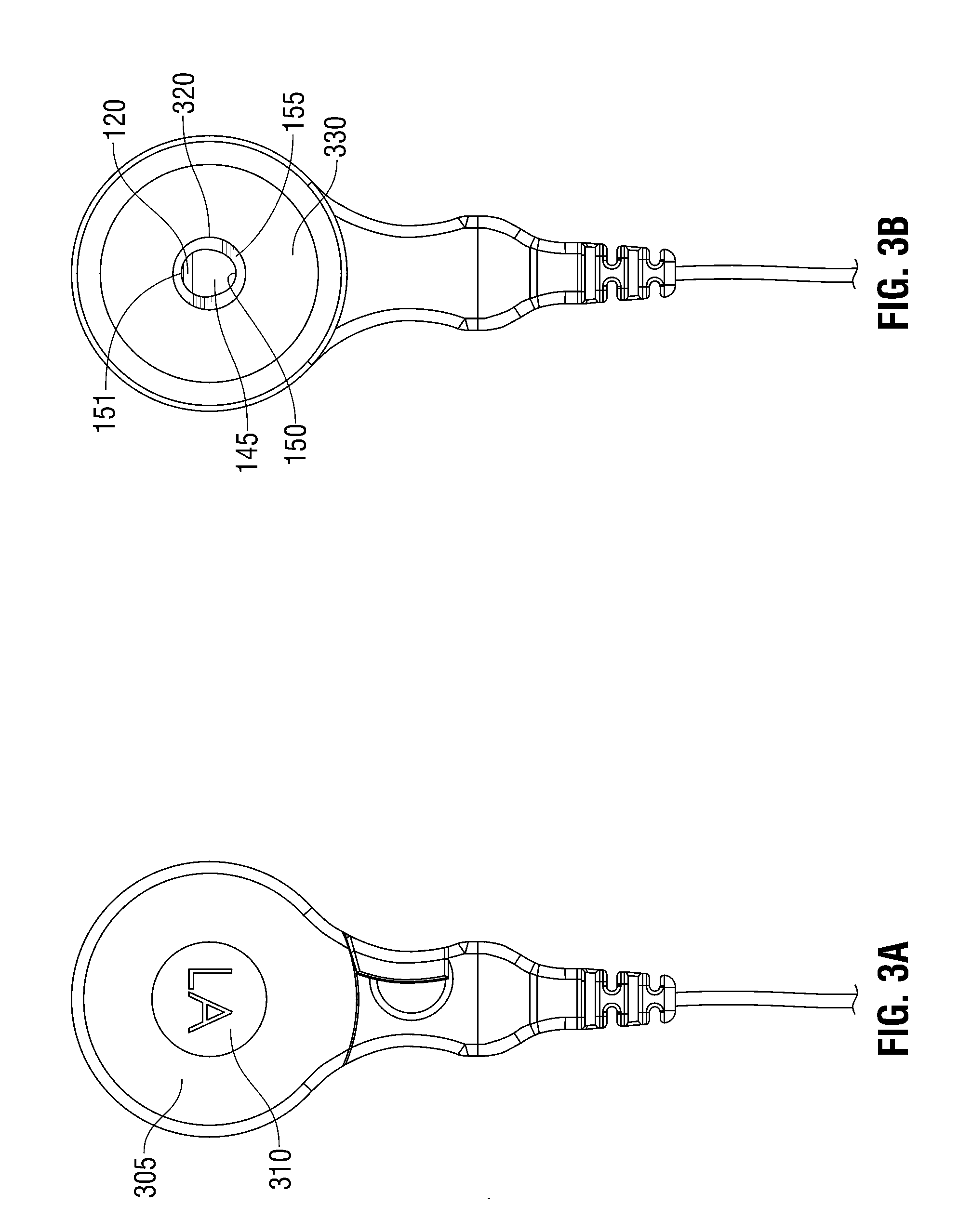
[0052]Referring to FIGS. 1, 2, and 3A, there is shown an embodiment of an ECG electrode connector 100 having a thumb cam lever 110. The connector 100 includes a housing 105 that includes a cavity 106, a pivot pin 115, and a thumb cam lever 110 having a...


PUM


Abstract

Disclosed is an ECG electrode lead wire connector which provides improved electrical and mechanical coupling of the ECG electrode press stud to the lead wire, provides enhanced ergonomics to the clinician, and may alleviate patient discomfort associated with the attachment and removal of ECG leads. The connector may be engaged and disengaged with little or no force imparted to the patient or the ECG pad, which significantly minimizes the risk of inadvertent dislodgement of the pad. In one embodiment the disclosed connector provides a thumb cam lever which affirmatively engages the press stud to the connector, and provides tactile feedback to the clinician that the connector is properly engaged. In other embodiments, the connector provides a pushbutton to enable the clinician to easily engage and disengage the connector from the ECG stud. The disclosed connectors may also decrease clinician fatigue, and may provide more reliable ECG results.

Description

CROSS-REFERENCE TO RELATED APPLICATION[0001]This application claims priority to U.S. Provisional Application Ser. No. 61 / 012,825, filed Dec. 11, 2007, the entirety of which is hereby incorporated by reference herein for all purposes.BACKGROUND[0002]1. Technical Field[0003]The present disclosure relates to biomedical electrodes, and in particular, to a biomedical electrode connector for attaching a lead wire to an electrocardiogram (ECG) electrode placed on a patient's body.[0004]2. Background of Related Art[0005]Electrocardiograph (ECG) monitors are widely used to obtain medical (i.e. biopotential) signals containing information indicative of the electrical activity associated with the heart and pulmonary system. To obtain medical signals, ECG electrodes are applied to the skin of a patient in various locations. The electrodes, after being positioned on the patient, connect to an ECG monitor by a set of ECG lead wires. The distal end of the ECG lead wire, or portion closest to the p...

Claims


Application Information

Patent Timeline
Patent Type & Authority Patents(United States)
IPC IPC(8): H01R4/48A61B5/308A61B5/274
CPCA61B5/0416A61B5/04286H01R13/6277H01R13/62933A61B5/04A61B2562/227H01R2101/00H01R2201/12Y10S439/909H01R24/20A61B5/274A61B5/303A61B5/24H01R13/193H01R13/639
Inventor SELVITELLI, DAVIDMEYER, PETER
Owner KPR U S LLC
Learn More