Vacuum envelope including self-aligning end shield, vacuum interrupter, vacuum circuit interrupter and method including the same

a vacuum circuit interrupter and self-aligning end shield technology, applied in the field of vacuum interrupters, can solve the problems of reducing productivity, slow furnace run time, and reducing the decoupling of various components

Active Publication Date: 2011-10-18
EATON INTELLIGENT POWER LTD
View PDF14 Cites 24 Cited by
  • Summary
  • Abstract
  • Description
  • Claims
  • Application Information

AI Technical Summary

Problems solved by technology

These, however, can slow furnace run times, reduce productivity, stick to the sub-assembly and / or shield radiant heat from braze joints causing various components to be decoupled.
In the event that the end shield is not properly secured in the vacuum interrupter, then electrical shorts can result.

Method used


Image

  • Vacuum envelope including self-aligning end shield, vacuum interrupter, vacuum circuit interrupter and method including the same
  • Vacuum envelope including self-aligning end shield, vacuum interrupter, vacuum circuit interrupter and method including the same
  • Vacuum envelope including self-aligning end shield, vacuum interrupter, vacuum circuit interrupter and method including the same

Examples


Embodiment Construction

[0036]As employed herein, the term “number” shall mean one or an integer greater than one (i.e., a plurality).

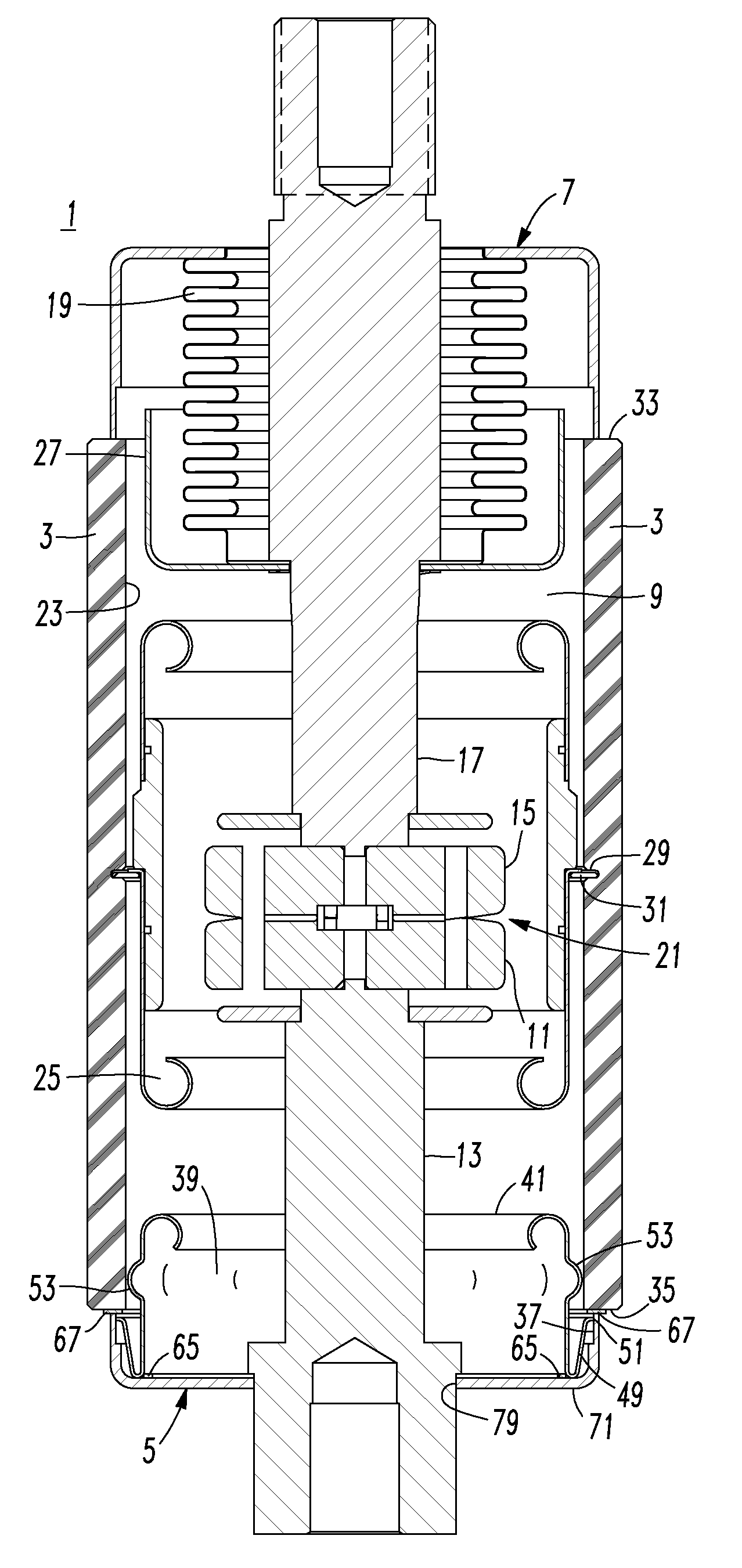
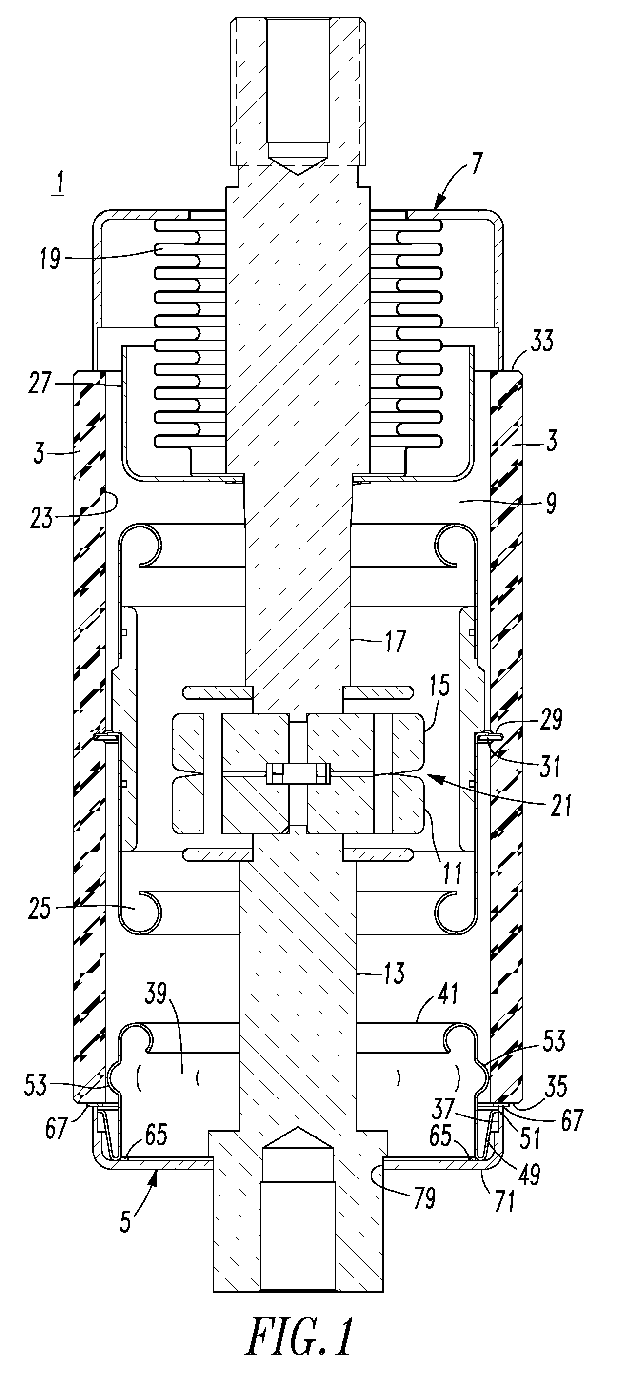
[0037]Referring to FIGS. 1, 7 and 8, a vacuum interrupter 1 is shown. The vacuum interrupter 1 includes an insulative tube, such as the example ceramic tube 3, which with end members 5 and 7 forms a vacuum envelope 9. A fixed contact 11 is mounted on a fixed electrode 13, which extends through the end member 5. A moveable contact 15 is carried by a moveable electrode 17 and extends through the end member 7. A bellows 19 forms a seal between the end member 7 and the moveable electrode 17 while allowing axial movement of the moveable electrode 17 to bring the moveable contact 15 into and out of contact with the fixed contact 11. The fixed contact 11 and moveable contact 15 form separable contacts 21, which when closed, complete an electrical circuit between the fixed electrode 13 and the moveable electrode 17, and when opened by axial movement of the moveable electrode 17 inte...


PUM


Abstract

A vacuum envelope is for a fixed contact mounted on a fixed electrode and a moveable contact mounted on a moveable electrode. The vacuum envelope includes a ceramic tube including a first open end and a second open end. A first end member is secured to the first open end. A second end member includes an inside surface and is secured to the second open end. A self-aligning end shield includes a first end having an opening therein, a second open end, an intermediate portion disposed between the first end and the end shield second open end, and a flange portion disposed from the end shield second open end. The flange portion extends outwardly from the intermediate portion and generally back toward the first end. The flange portion includes an edge engaging the inside surface of the second end member, and is normally offset from the ceramic tube.

Description

BACKGROUND OF THE INVENTION[0001]1. Field of the Invention[0002]This invention pertains generally to vacuum interrupters which provide protection in electric power circuits and, more particularly, to vacuum interrupters or vacuum envelopes including end shields that provide a self-alignment function. The invention also pertains to a self-alignment method for ends shields of vacuum interrupters. The invention further pertains to vacuum circuit interrupters including vacuum interrupters having end shields that provide a self-alignment function.[0003]2. Background Information[0004]Vacuum circuit interrupters (e.g., without limitation, vacuum circuit breakers; vacuum switches; load break switches) provide protection for electrical systems from electrical fault conditions such as current overloads, short circuits, and low level voltage conditions. Typically, vacuum circuit interrupters include a spring-powered or other suitable operating mechanism, which opens electrical contacts inside ...

Claims


Application Information

Patent Timeline
Patent Type & Authority Patents(United States)
IPC IPC(8): H01H33/66
CPCH01H33/66261H01H2033/66276
Inventor TRONDSEN, WILLIAM J.
Owner EATON INTELLIGENT POWER LTD
Why Eureka
Try Eureka