
Delivery device

a delivery device and delivery technology, applied in the field of delivery devices, can solve the problems of inability of needles and syringes to target key cells in the outer skin layer, serious limitation of many existing and emerging strategies for prevention, treatment and monitoring a range, and many of these approaches remain untested for complex entities such as vaccines and immunotherapies

Active Publication Date: 2011-11-08
VAXXAS PTY LTD
View PDF12 Cites 53 Cited by
  • Summary
  • Abstract
  • Description
  • Claims
  • Application Information

AI Technical Summary

Problems solved by technology

Limitations of intradermal injection include: cross-contamination through needle-stick injuries in health workers; injection phobia from a needle and syringe; and most importantly, as a result of its comparatively large scale and method of administration, the needle and syringe cannot target key cells in the outer skin layers (FIG. 11 (a)).
This is a serious limitation to many existing and emerging strategies for the prevention, treatment and monitoring of a range of untreatable diseases.
Many of these approaches remain untested for complex entities such as vaccines and immunotherapies.
Moreover, they do not specifically deliver entities within key skin cells.
Furthermore, as a result of the concentrated jet momentum, many skin cells die.
Delivery into the dermis also leads to patients reporting pain from injection.
The ability of this “scatter gun” approach to deliver genes and drugs to epidermal cells is highly limited and sensitive to biological variability in skin properties on the dynamic high strain rate ballistics process.
)—the result is a large variation in penetration depth.
The compound effect of these two (and other) sources of variability is the gene gun / biolistics process does not consistently target epidermal cells-leading to inconsistent biological responses (e.g. in DNA vaccination).
This means that the tissue is more difficult to penetrate as the particle impact velocity is increased.
Moreover, when the microparticles successfully target cells, there is a significant probability they kill the cells they target.
This mechanism of ballistic particle penetration killing cells negatively affects the ability of the direct and efficient delivery of genes and drugs to the cells.
However, another limitation of the gene gun is that it is unsuitable in delivering sub-micron sized particles to cells.
Indeed from FIG. 14 we see delivery to a 20 μm depth would need an impact velocity of ˜6000 m / s, which is impractical for two reasons: 1) these hypervelocity conditions can not be safely achieved with a system configured for human use (they are usually achieved with massive free-piston shock tunnels); 2) even if 6000 m / s was obtained in the free-jet, a gas impingement region above the skin would seriously decrease the particle velocity—it is possible that the particle would not even hit the skin at all.
Interestingly if a method was conceived to safely and practically deliver nanoparticles to the skin at higher velocity (e.g. the stated case of an 100 nm radius gold particle at a velocity of ˜6000 m / s), the cell death benefit of smaller scale would be offset by higher peak stresses-killing more cells—and higher strain rates that are likely to further “toughen” the skin, making delivery even more difficult.
Although this is a very efficient gene and bioagent delivery route, the drawback is that such precise targeting by direct microinjection can only be achieved one cell at a time and with great difficulty to the operator in vivo.
Hence, the method is slow, laborious and impractical.
These microneedles array patch technologies have achieved only limited success to date.
Also, unlike ballistic microparticle delivery, these projections are removed from the tissue-alleviating the possibility of adverse effects of “carrier” materials delivered to the body, long term.
However, unlike biolistic targeting (FIG. 11(b)), and the direct injection of cells (FIG. 11(c)), these microneedle arrays do not have the advantage of readily and directly targeting inside the skin cells.
Whilst U.S. Pat. No. 5,457,041 describes a patch for targeting cells, this is only suitable for use in vitro, and requires specialised apparatus to direct the micro-needles towards identified cells.
As a result, this makes the device unsuitable for use in clinical environments, and limits the ability of the device to elicit a desired biological response.

Method used


Image

  • Delivery device
  • Delivery device
  • Delivery device

Examples


specific examples

[0282]A number of specific examples will now be described.

Transfection Probability

[0283]In this example, which focuses on the transfection of Langerhans cells, a number of additional practical considerations may also be taken into account.

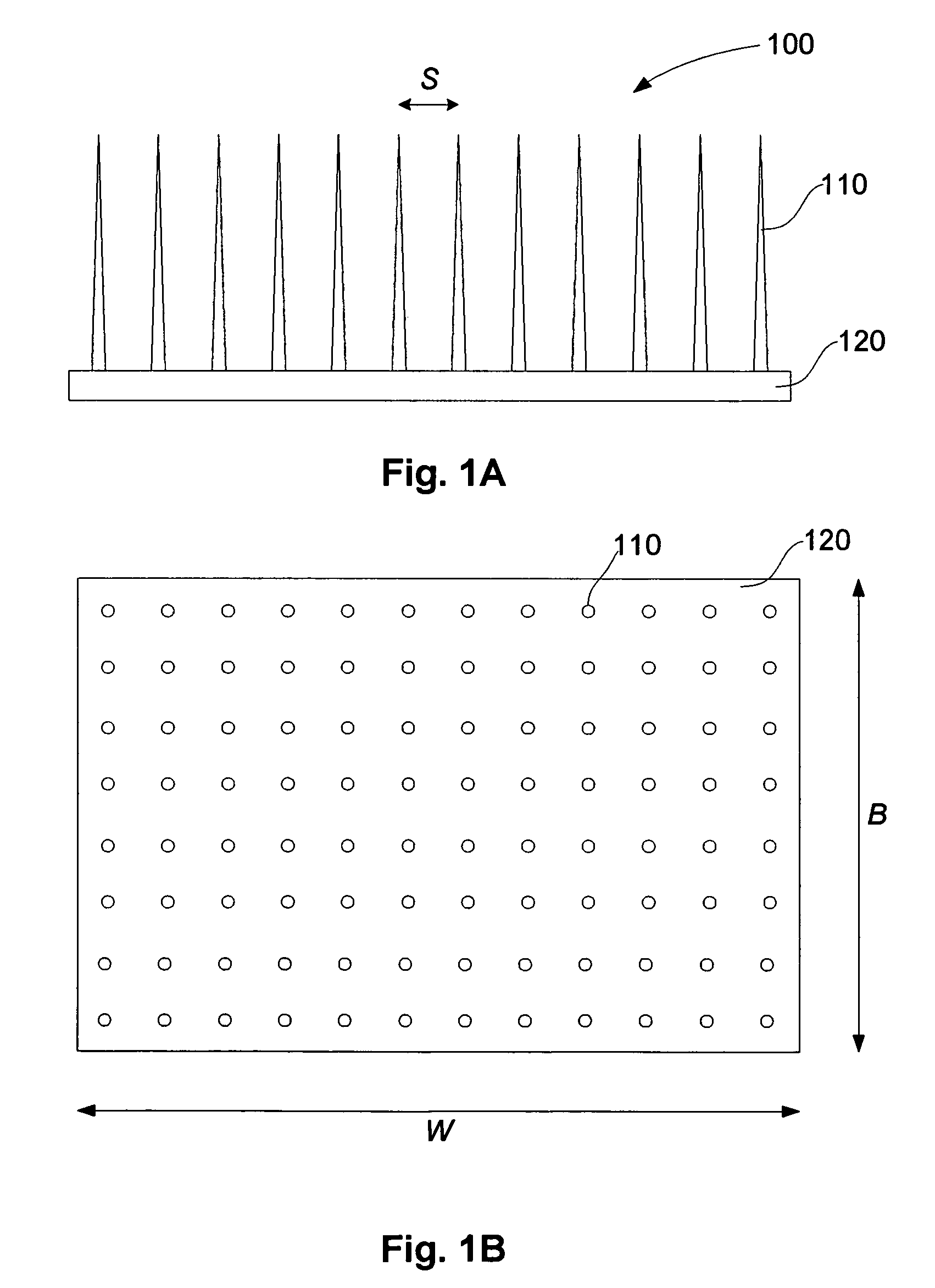
[0284]In particular, if the model of a point targeting section with no radius is used, this predicts an idealised projection spacing S=6.5 μm, as used in the example of FIG. 8. In this case, the LC diameter is ˜10 μm, so that to satisfy the requirements set out above, namely that S≦dc, so S≧10 μm.

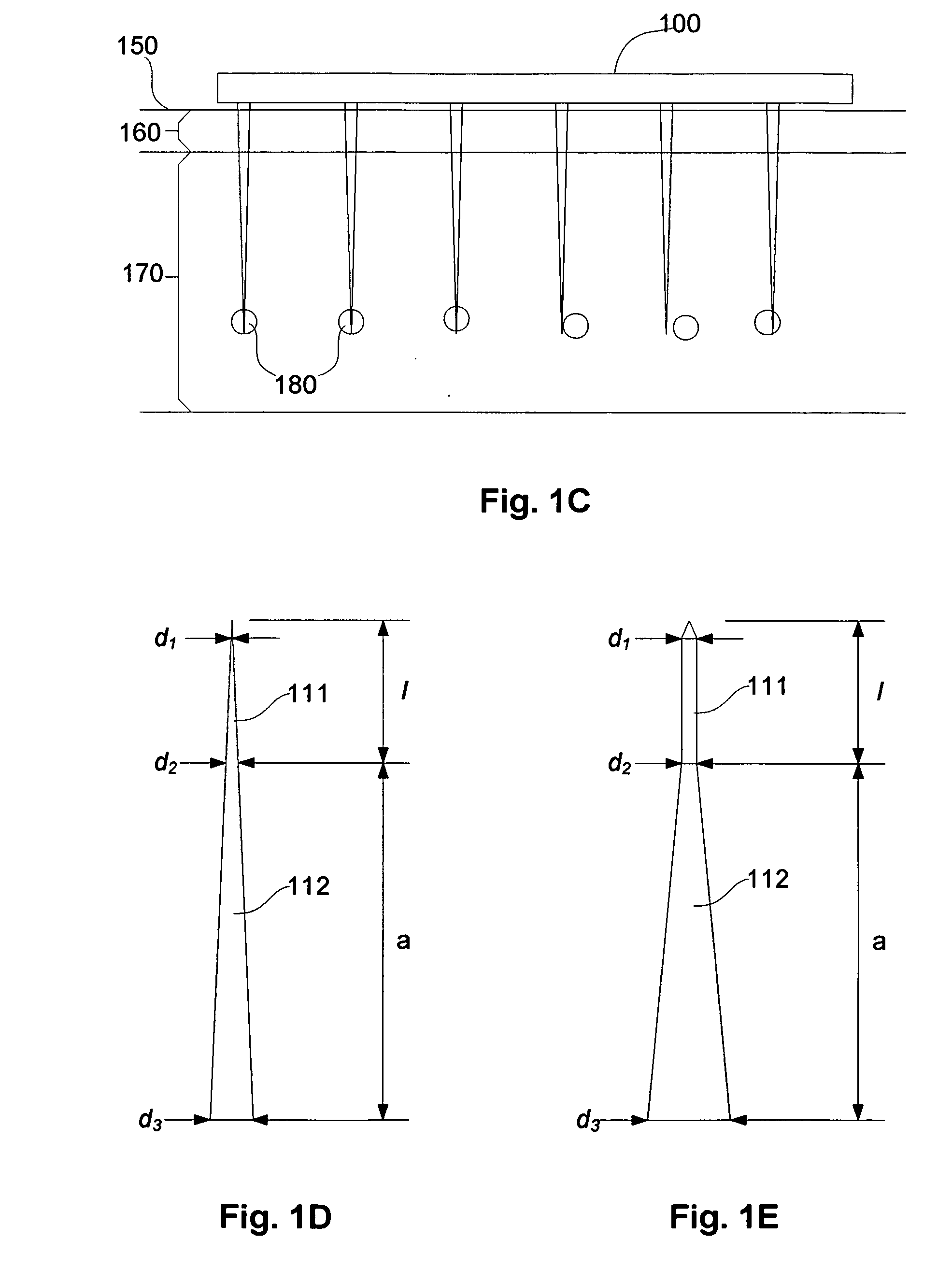
[0285]Also, for structural reasons, the diameter of the base of the projections d3 is likely to be above 6.5 μm, and a “clearance” will be needed between each projection, so for practical reasons, the minimum projection spacing (S) is at least 10 μm.

[0286]FIG. 8 shows an example of the Transfection Probability vs Needle Spacing, for targeting of Langerhans cells with a spacing of 32 μm. The S≧dc criterion and practical considerations of minimum size of the...


PUM


Abstract

A device for delivery of material or stimulus to targets within a body to produce a desired response, the targets being at least one of cells of interest, cell organelles of interest and cell nuclei of interest. The device includes a number of projections for penetrating a body surface, with the number of projections being selected to produce a desired response, and the number being at least 500. A spacing between projections is also at least partially determined based on an arrangement of the targets within the body.

Description

CROSS-REFERENCE TO RELATED CASE[0001]The current application is a continuation-in-part (CIP) of International Application Number PCT / GB2005 / 000336 which designates the U.S. and has an International Filing Date of 31 Jan. 2005 and which was published as International Publication No. WO2005 / 072630 on 11 Aug. 2005. The entirety of International Application Number PCT / GB2005 / 000336 is hereby incorporated herein by reference.BACKGROUND OF THE INVENTION[0002]The present invention relates to a device for delivery of material or stimulus to targets within a body to produce a desired response, and in particular to a device including a number of projections for penetrating a body surface. The invention can also relate to devices for delivering bioactive substances and other stimuli to living cells, to methods of manufacture of the device and to various uses of the device.DESCRIPTION OF THE PRIOR ART[0003]The reference in this specification to any prior publication (or information derived from...

Claims


Application Information

Patent Timeline
Patent Type & Authority Patents(United States)
IPC IPC(8): A61N1/30A61B17/20A61M25/00A61M37/00
CPCA61B17/205A61M37/0015B33Y80/00A61M2037/0046
Inventor KENDALL, MARK ANTHONY FERNANCE
Owner VAXXAS PTY LTD
Learn More