Pulse-width modulated (PWM) audio power amplifier having output signal magnitude controlled pulse voltage and switching frequency

a power amplifier and pulse voltage technology, applied in amplifiers, amplifiers with semiconductor devices only, amplifiers with etc., can solve the problems of large electromagnetic interference (emi) generated by class-d amplifiers, audio power output stage amplifiers consume the bulk of wasted power in an audio system, etc., and achieve the effect of reducing the switching frequency of the power amplifier

Active Publication Date: 2012-01-10
CIRRUS LOGIC INC
View PDF18 Cites 110 Cited by
  • Summary
  • Abstract
  • Description
  • Claims
  • Application Information

AI Technical Summary

Benefits of technology

[0011]The switching frequency of the switching power amplifier may be reduced when higher levels of output voltage are selected, indicating a higher level output signal. Any noise or distortion introduced by the lower switching rate will be masked by the higher amplitude output signal, and the lower pulse rate at the amplifier output serves to reduce EMI during periods when the higher pulse voltage is generally selected to generate the higher amplitude output signal.

Problems solved by technology

Audio power output stage amplifiers consume the bulk of the wasted power in an audio system.
However, the electromagnetic interference (EMI) generated by class-D amplifiers can be substantial, in contrast to that of linear amplifiers, in which generated EMI is almost nonexistent.
However, since the connection to a transducer is frequently a substantial length of wiring, and high frequency components of unfiltered switching pulses are therefore present on the wiring, the EMI generated by an inductor-less design is generally substantially greater than the EMI generated by designs including an inductor.

Method used


Image

  • Pulse-width modulated (PWM) audio power amplifier having output signal magnitude controlled pulse voltage and switching frequency
  • Pulse-width modulated (PWM) audio power amplifier having output signal magnitude controlled pulse voltage and switching frequency
  • Pulse-width modulated (PWM) audio power amplifier having output signal magnitude controlled pulse voltage and switching frequency

Examples


Embodiment Construction

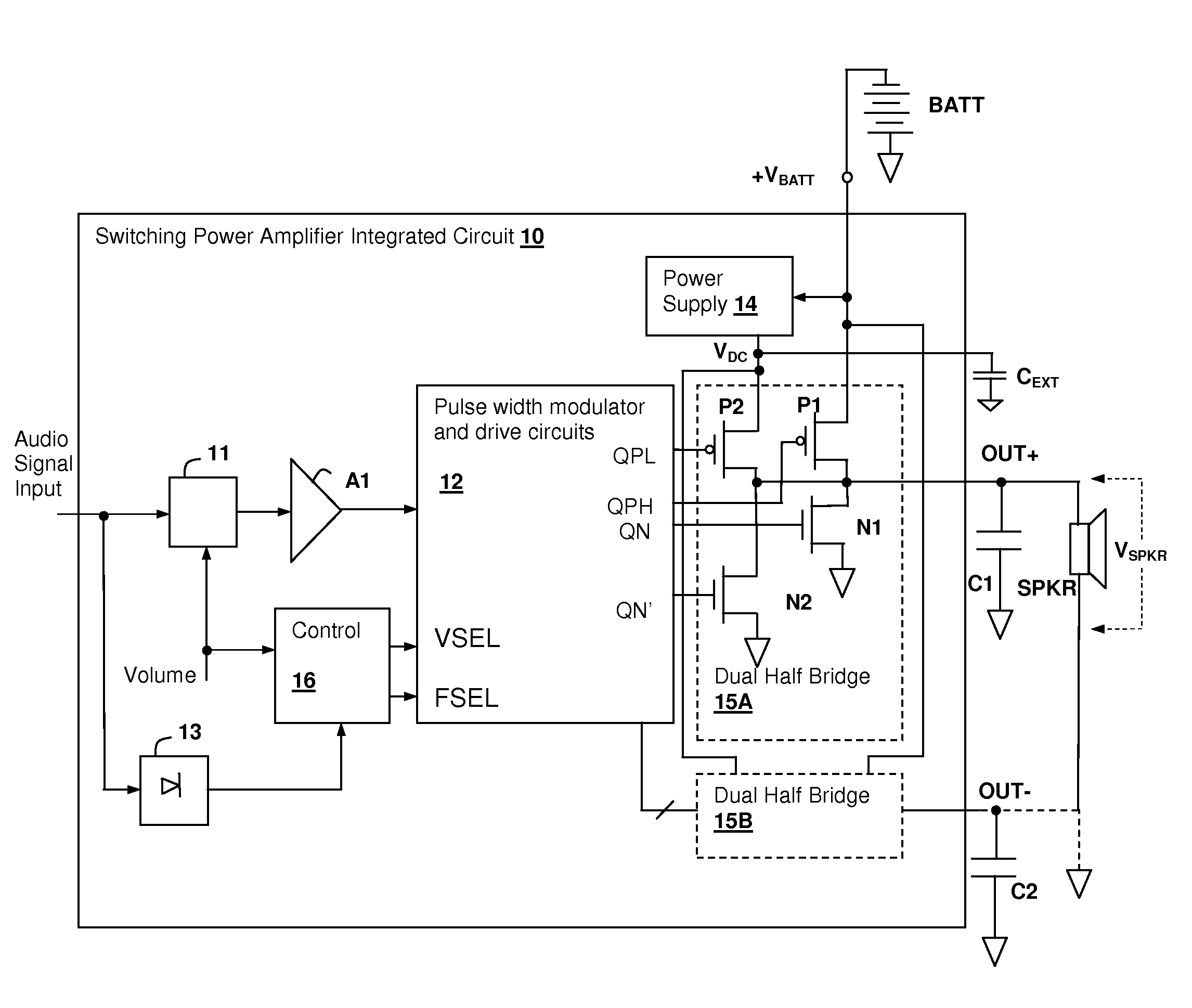
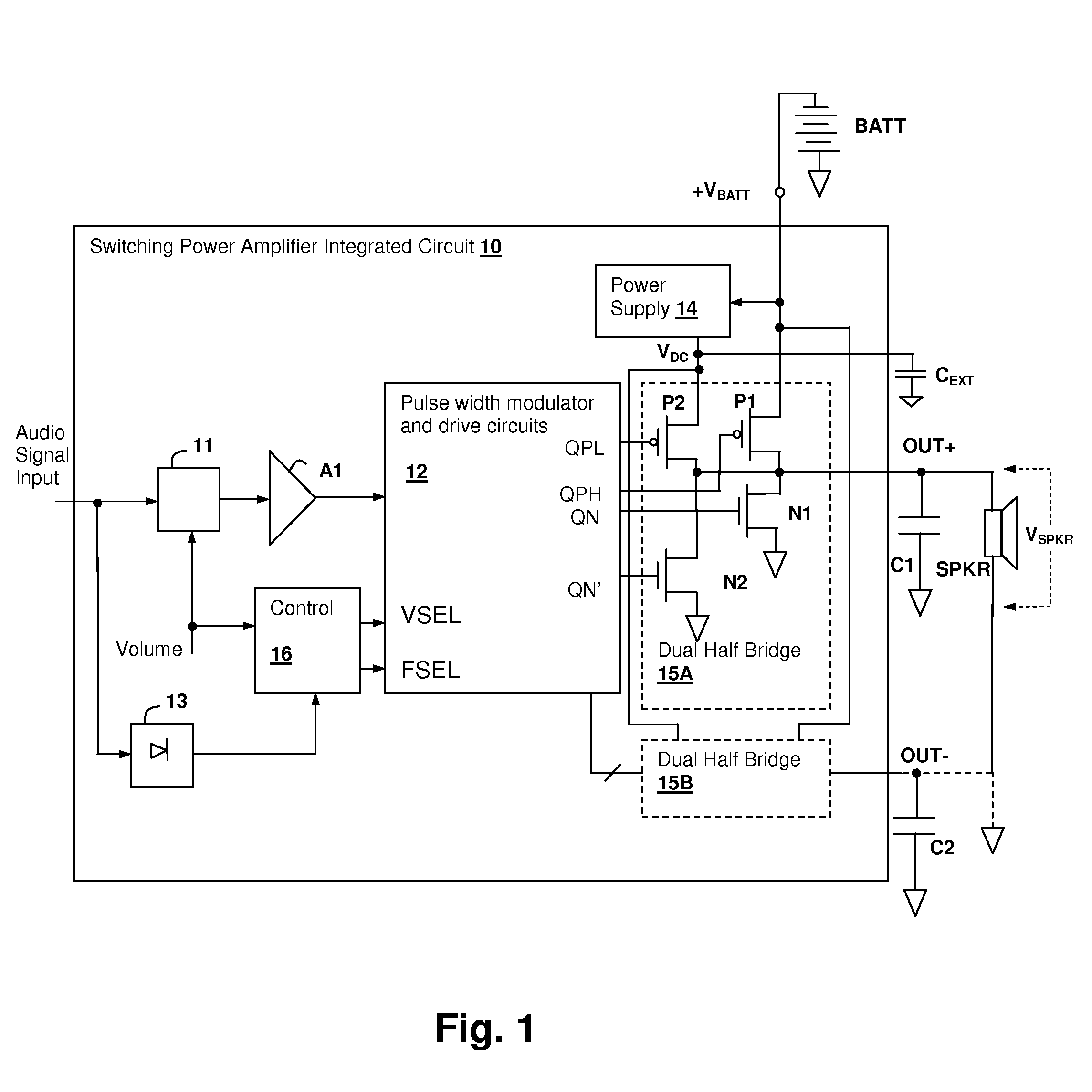
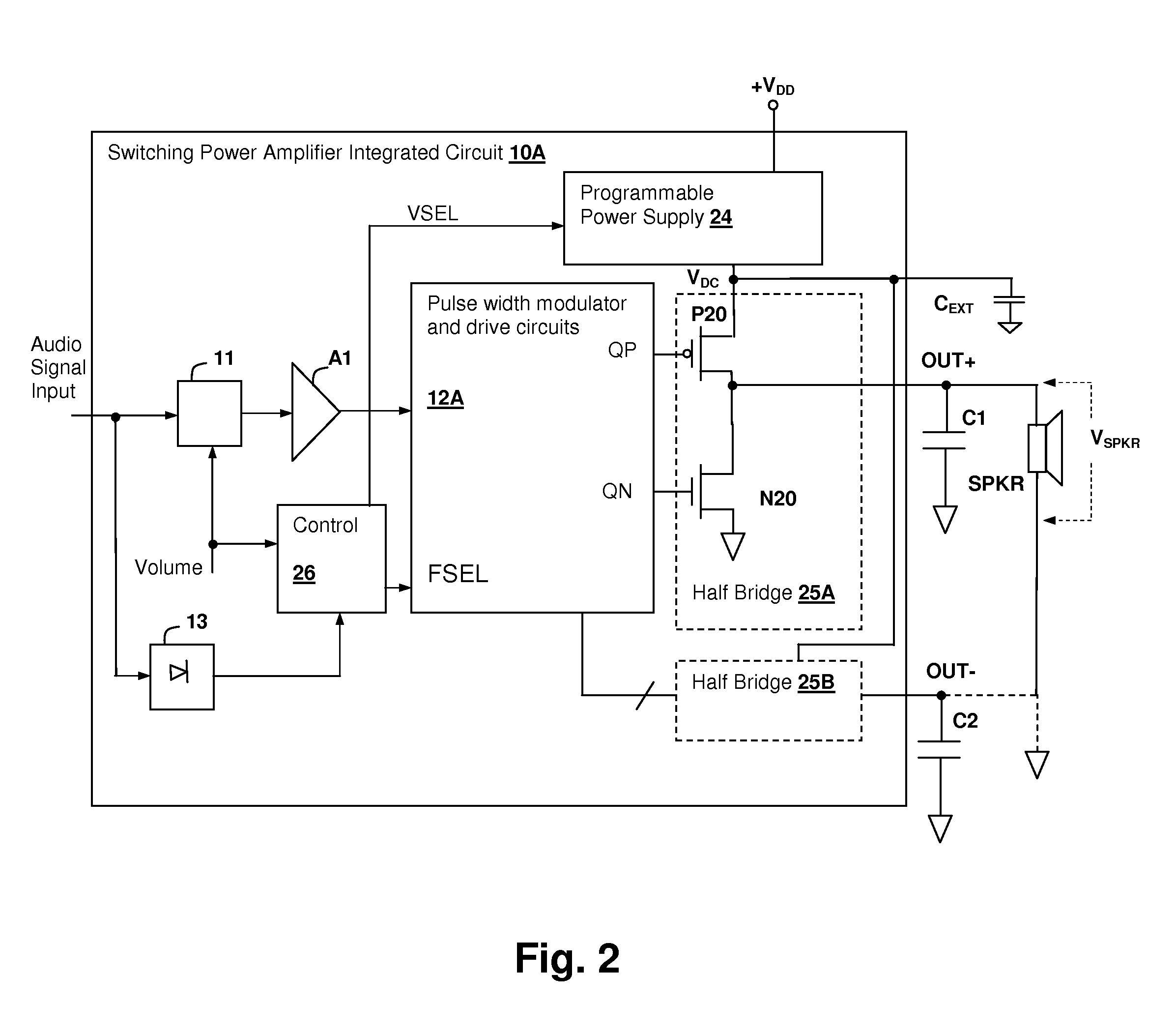
[0018]The present invention encompasses a pulse-width modulated (PWM) audio switching power amplifier circuit and method of operation in which an indication of the output signal amplitude: either a volume control value that is applied to the input signal or a detected signal level, is used to control the pulse voltage provided to the output of the amplifier. At lower output signal levels, the power supply voltage can be reduced, which generates a lower level of electromagnetic interference (EMI), especially in inductor-less applications in which the wires connecting the amplifier to the transducer have pulse waveforms. The switching frequency of the power amplifier may also be controlled in conformity with the indication of the output signal amplitude, so that when higher voltage pulses are generated on the amplifier output, a lower switching frequency is used. The lower switching frequency reduces EMI by reducing the number of pulses generated over a given interval, and thus the en...


PUM


Abstract

An audio switching power amplifier having an output pulse voltage selected in conformity with an indication of the output signal amplitude provides lower electromagnetic interference (EMI) in class-D amplifier implementations, in particular, in inductor-less designs. The output pulse voltage may be selected by providing multiple switching circuits, such as half or fully bridge switches, with each switching circuit connected to a different power supply. One of the switching circuits is activated by the switching controller, while the others are disabled, providing selection of the output pulse voltage. Selection of a lower pulse voltage, when the maximum voltage is not required, reduces the generated EMI. The switching frequency of the class-D amplifier may also be controlled in conformity with the output signal amplitude, so that at higher output levels a lower switching rate is selected, reducing the generated EMI.

Description

[0001]The present U.S. patent application claims priority under 35 U.S.C. §119(e) to U.S. Provisional Patent Application 61 / 168,968 filed on Apr. 14, 2009.BACKGROUND OF THE INVENTION[0002]1. Field of the Invention[0003]The present invention relates generally to integrated circuit switching power amplifiers, and more specifically, to a pulse-width modulated (PWM) power amplifier in which the pulse voltage and / or switching frequency are dependent on output signal amplitude.[0004]2. Background of the Invention[0005]Audio power output stage amplifiers consume the bulk of the wasted power in an audio system. In analog amplifiers, the difference between the voltage of the power supply rails and the voltage of the output signal is a voltage drop that determines the wasted power in combination with the instantaneous load current. Raising the efficiency of power amplifiers has typically been performed in one of two ways: either controlling the voltage of the power supply rails of a linear am...

Claims


Application Information

Patent Timeline
Patent Type & Authority Patents(United States)
IPC IPC(8): H03F3/217H03F3/04
CPCH03F3/217H03F2200/03H03F2200/114H03F2200/351
Inventor ZHANG, LINGLISHEN, DANGABORIAU, JOHANNSWANSON, ERIC J.
Owner CIRRUS LOGIC INC
Why Eureka
Try Eureka