Ambulating ankle and knee joints with bidirectional dampening and assistance using elastomeric restraint

a technology of ambulating ankle and knee joints and elastomeric restraints, which is applied in the field of hinge or joint assemblies for orthotics, prosthetics, or rehabilitation devices, can solve the problems of human knee and ankle systems, patient's ability, and the proneness of traditional orthotic devices to rigid movement, and achieves dampening the shock absorption feature, high stance control moments, and resistance to ankle and knee flexion

Inactive Publication Date: 2012-01-24
ULTRAFLEX SYST
View PDF90 Cites 7 Cited by
  • Summary
  • Abstract
  • Description
  • Claims
  • Application Information

AI Technical Summary

Benefits of technology

[0008]The present invention provides an orthotic, prosthetic, or rehabilitative device that assists, or takes the place of, muscles that are weak or absent, and that normally control and prevent the ankle or knee from lagging during swing-through extension, from buckling at heel strike through terminal stance on the balls and toes of the foot, and from buckling during sit-to-stand from a chair. The device of the present invention provides controlled, multi-position rotational motion in the extension direction to prevent knee buckling from sit-to-stand through a ratcheting, step-advance feature. Further, resistance to ankle and knee flexion is provided through an elastomeric spring, enabling a dampening shock absorption feature, the elastomeric spring also assisting knee movement from a flexed attitude during the swing-phase to a straight leg position (extension) just prior to initial contact with the floor (heel strike). Elastomeric material characteristics further enable relatively high stance control moments to be effectively dampened, while swing return moments and rate of return (or hysteresis) are far less in magnitude and velocity, thereby mimicking normal muscle function.
[0009]The present invention provides a weight bearing strut assembly capable of supporting the human frame in the act of walking, while enabling a leg to which it is attached to bend in a normal and natural ambulatory manner. While walking, the present invention provides shock absorption during heel strike and an accelerating or urging capability to a forward moving lower leg during swing from ankle and knee flexion to extension in preparation for receiving weight upon heel strike. Both the dampening, shock absorption function and the urging capability or force is adjustable, with a degree of force and angle of rotation upon which the force is provided being adaptable to suit individual needs. The present invention incorporates the normal and natural ambulatory motion with the security of a step-advance feature, ensuring support of the knee during weight bearing extension (e.g., rising from a sitting position). The elastomeric spring can be adapted to reproduce the force deflection curve of any bodily muscle, by varying the size, shape, and / or characteristics of the elastomeric spring.

Problems solved by technology

The human knee and ankle systems can suffer a number of pathologies that affect the patient's ability to bear this weight and walk (with or without pain).
However, traditional orthotic devices are prone to rigidity in movement, and do not provide flexion and extension capabilities approximating that of a healthy, normal joint.
Further, an orthotic device closely approximating normal joint and muscle motion can help prevent a learned disuse of certain muscles and movements during a period of prolonged immobility and / or rehabilitation, whereby the brain settles on compensatory muscle use and movements that greatly inhibit mobility, eventually requiring heavier and more restrictive devices resulting in more noticeable limp and an inefficient gait.

Method used


Image

  • Ambulating ankle and knee joints with bidirectional dampening and assistance using elastomeric restraint
  • Ambulating ankle and knee joints with bidirectional dampening and assistance using elastomeric restraint
  • Ambulating ankle and knee joints with bidirectional dampening and assistance using elastomeric restraint

Examples


first exemplary embodiment

An Operating Description of the First Exemplary Embodiment

[0092]FIGS. 5a-5e illustrate the hinge assembly 14 of the knee brace 10 in various positions of use, each position employing one or more features of the present invention. FIG. 5a illustrates the hinge assembly 14 in a position of full flexion, with the angled shoulder 58 of the distal half joint 32 bearing against the rear edge 60 of the proximal half joint 30, the bearing relationship serving as a stop to rotational movement in a flexion direction. At full flexion, approximately 60° exist between the upper and the lower members 15, 16. Accordingly, approximately 120° defines a complete range of motion between full flexion and full extension.

[0093]FIG. 5a shows the lock slide 44 engaging respective spur teeth 62 of the ROM disk 34, thereby enabling sit-to-stand support, for users having difficulty rising from a sitting position, through one-way, step-advance ratcheting. As shown in FIG. 5a, rotational movement toward extensi...

embodiment

Bi-directional Ankle Embodiment

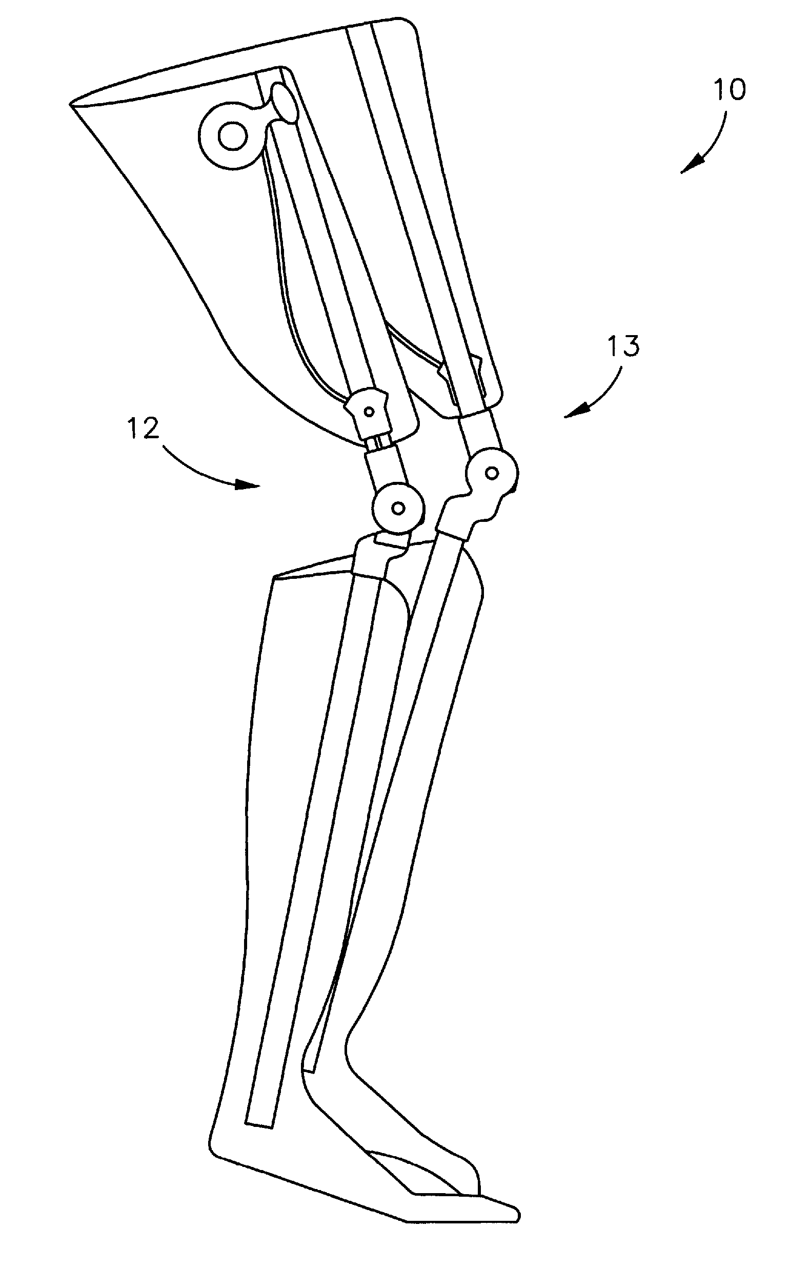
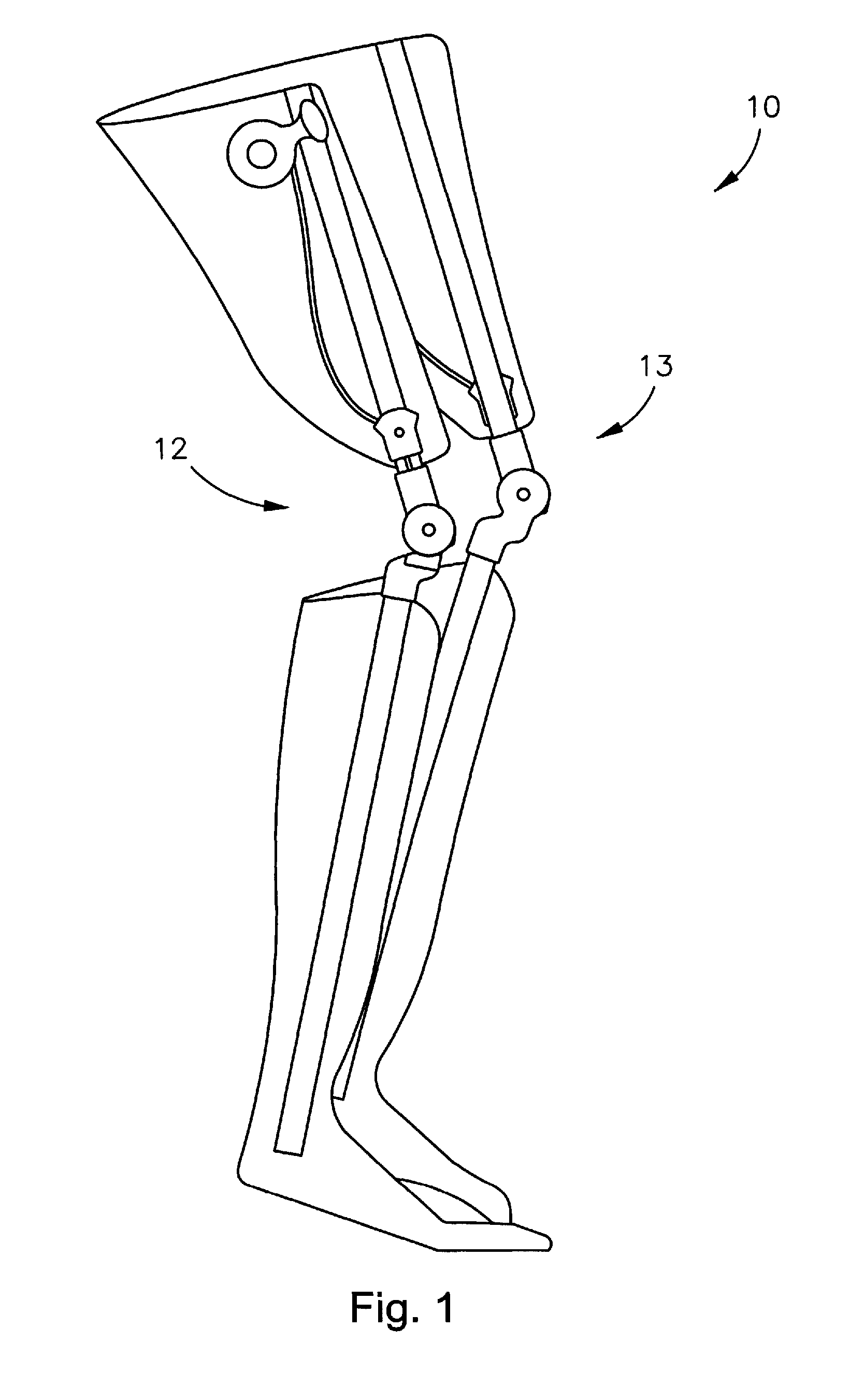
[0132]FIGS. 10a and 10b illustrate a bi-directional ankle embodiment, or ankle joint 200, of the present invention. The bi-directional ankle joint 200 is shown mounted onto a ground reaction AFO, or leg and foot brace 201. The leg and foot brace 201 includes leg beams 202 mounted under a plastic shell 204 of the brace 201 to insure intimate fit and low profile. Two bi-directional ankle joints 200 are included in the brace 201, and each include a low profile-high support contoured strut 206 (proximal and distal), thereby allowing in-shoe wear of the brace 201 without requiring increased size shoe.

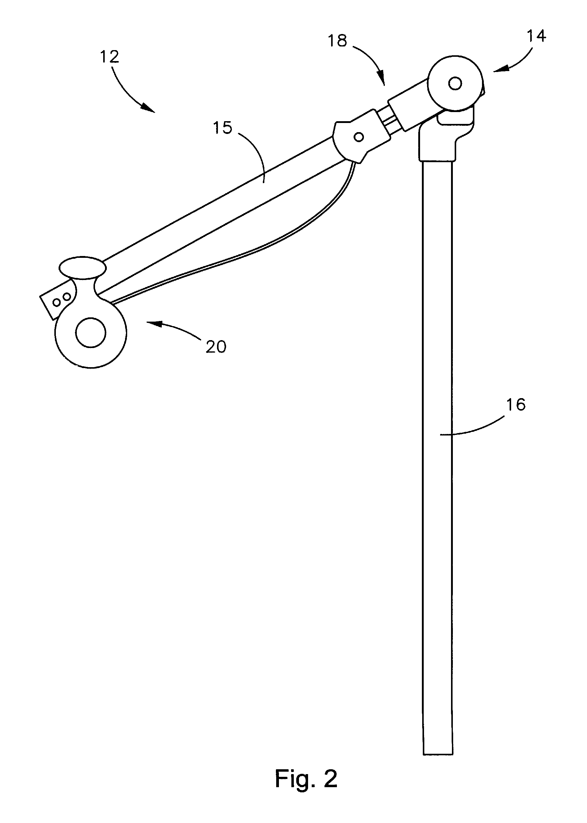
[0133]FIGS. 11a and 11b illustrate the bi-directional ankle joint 200 alone. The strut 206 is low profile and slim, with three mounting holes 208 that follow foot anatomy and hug the respective surface of the foot. The ankle hinge 210 has a cupola design, and includes an outer 211 and inner 212 surface that fits perfectly over the bony prominence of the ankle, ...


PUM


Abstract

A hinge or joint assembly includes a first member movably connected to a second member to allow angular displacement of the first member relative to the second member in each of extension and flexion (clockwise and counterclockwise) directions, where one elastomeric spring restrains angular displacement in a flexion position, and another elastomeric spring restrains angular displacement in an extension position. In each direction, the angular movement is dampened through compression of the respective elastomeric spring. After dampening the movement in either direction, returning movement is assisted through decompression of the respective elastomeric spring. Alternatively, one or more elastomeric springs are arranged to both dampen through compression and assist through decompression angular movement in each of the flexion and extension directions. The elastomeric spring can provide a pre-determined force deflection curve in compression and an independent rate of return hysteresis in decompression. The elastomeric springs could be urethane.

Description

RELATED APPLICATIONS[0001]This application is a continuation-in-part (CIP) of U.S. application Ser. No. 10 / 423,435, filed Apr. 25, 2003, entitled “AMBULATING KNEE JOINT,” and claims benefit of U.S. Provisional Application Ser. No. 60 / 736,922, filed Nov. 15, 2005, entitled “AMBULATING ANKLE & KNEE JOINTS WITH BIDIRECTIONAL DAMPENING AND ASSISTANCE USING ELASTOMER RESTRAINTS”.[0002]U.S. application Ser. No. 10 / 423,435 claims benefit of the following U.S. Provisional Applications Application Ser. No. 60 / 377,119, filed Apr. 25, 2002, entitled “AMBULATING KNEE JOINT WITH RANGE OF MOTION (ROM) DISC AND OVERRIDE FEATURE;” application Ser. No. 60 / 417,268, filed Oct. 9, 2002, entitled “AMBULATING KNEE JOINT;” application Ser. No. 60 / 427,777, filed Nov. 20, 2002, entitled “AMBULATING KNEE JOINT;” and application Ser. No. 60 / 455,809, filed Mar. 19, 2003, entitled “AMBULATING KNEE JOINT.” All of the above-noted related applications are incorporated herein by this reference.FIELD OF THE INVENTIO...

Claims


Application Information

Patent Timeline
Patent Type & Authority Patents(United States)
IPC IPC(8): A61F5/00
CPCA61F5/0125A61F5/0127A61F2005/0139A61F2005/016A61F2005/0167A61F2005/0179
Inventor DEHARDE, MARKVINSHTOK, YEVGENIY
Owner ULTRAFLEX SYST
Why Eureka
Try Eureka