Implant subsidence control

a subsidence control and implant technology, applied in the field of implant device, can solve the problems of steep slope of load-deflection curve, easy bending of devices, and stiffness of devices for such designs

Inactive Publication Date: 2012-01-24
RSB SPINE
View PDF59 Cites 104 Cited by
  • Summary
  • Abstract
  • Description
  • Claims
  • Application Information

AI Technical Summary

Problems solved by technology

Device stiffness might be an issue for such designs.
However, when formed into the shape of a structure like a paperclip it is easily bent.
The slope of the load-deflection curve would be steep.

Method used


Image

  • Implant subsidence control
  • Implant subsidence control
  • Implant subsidence control

Examples


Embodiment Construction

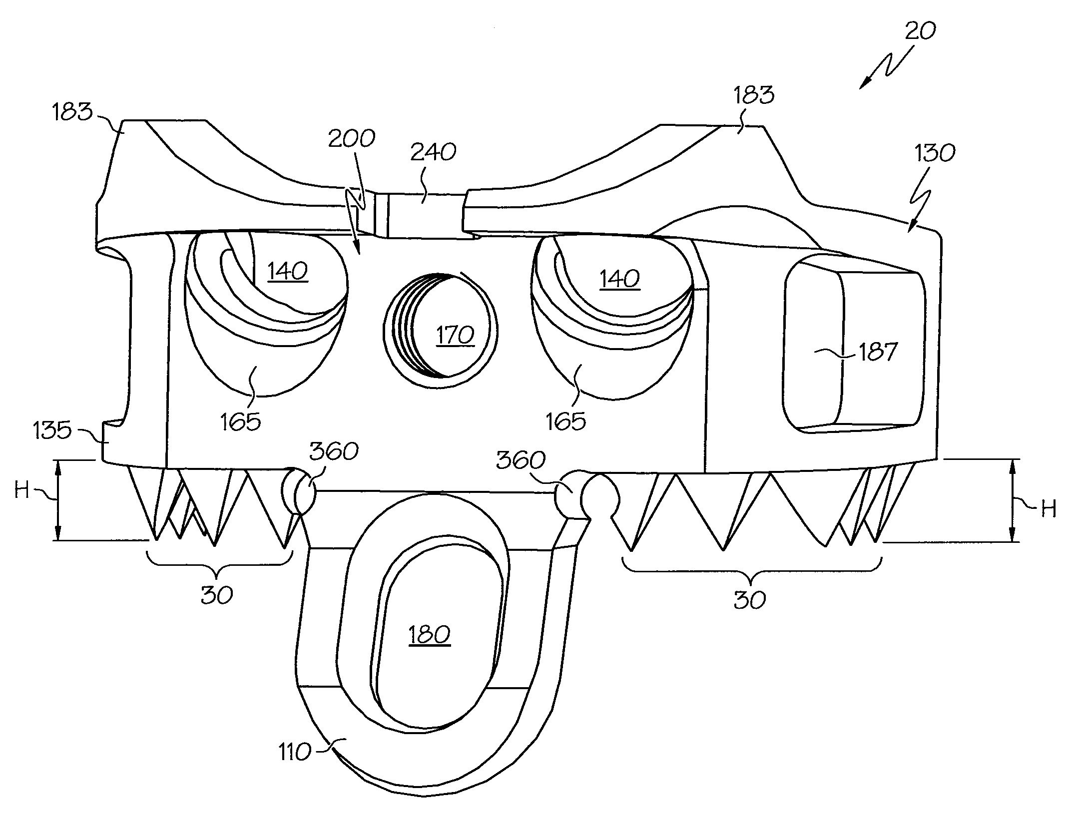
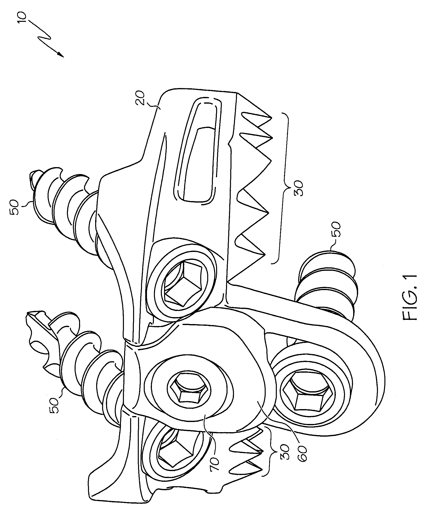
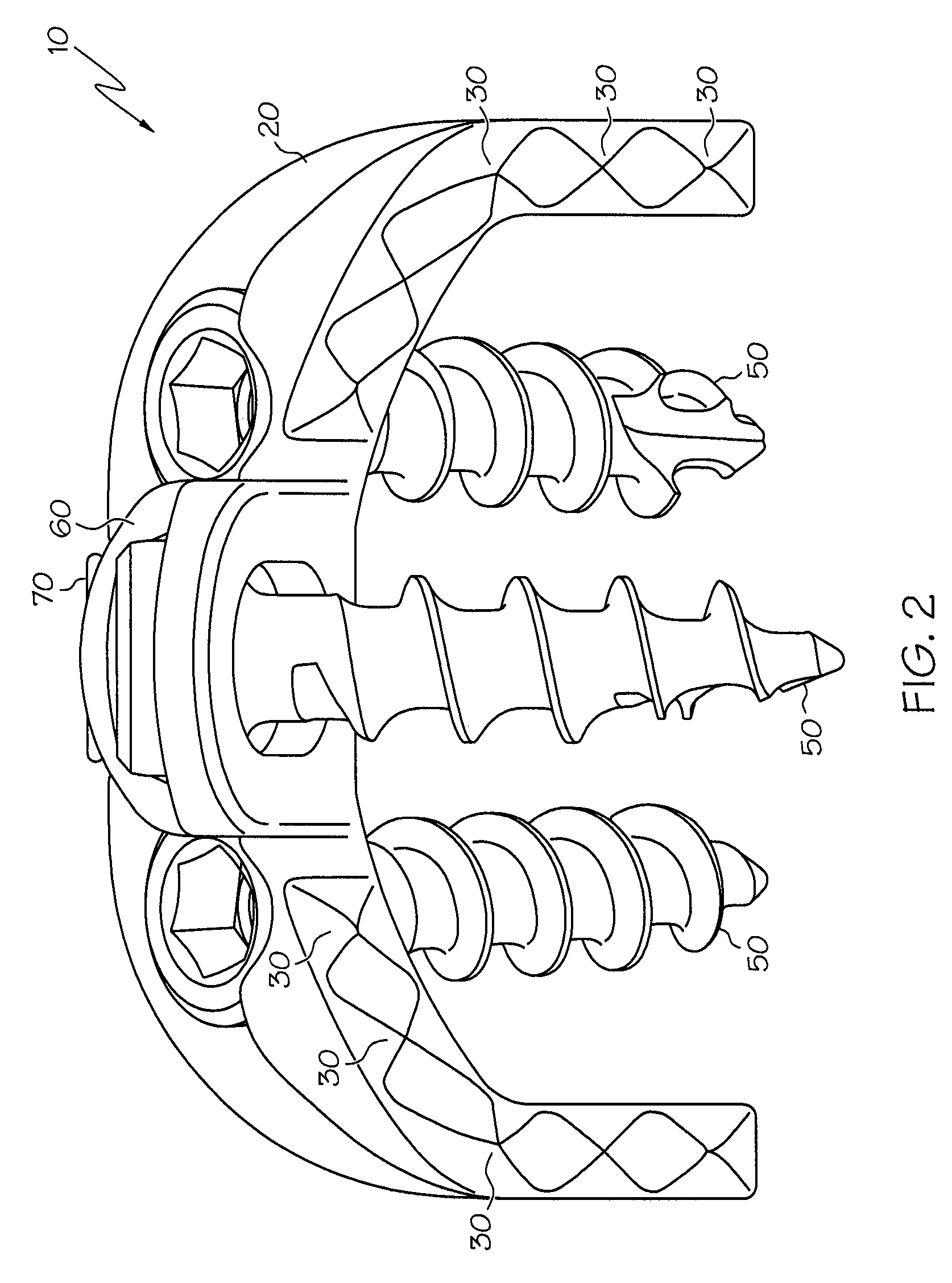
[0040]The present invention relates to an implant device, such as an interbody device, having subsidence control. The present invention will now be described with reference to the drawings, wherein like reference numerals are used to refer to like elements throughout. It is to be appreciated that the various drawings are not necessarily drawn to scale from one figure to another nor inside a given figure, and in particular that the size of the components are arbitrarily drawn for facilitating the understanding of the drawings. In the following description, for purposes of explanation, numerous specific details are set forth in order to provide a thorough understanding of the present invention. It may be evident, however, that the present invention can be practiced without these specific details. Additionally, other embodiments of the invention are possible and the invention is capable of being practiced and carried out in ways other than as described. The terminology and phraseology ...


PUM


Abstract

An interbody device for the fixation and support of adjacent bone bodies includes a body for implantation at a location between the two vertebrae and one or more protrusions extending from the body. The protrusion(s) are configured for engagement with one of the vertebrae upon implantation and for progressive penetration into the vertebra over a period of time subsequent to the implantation.

Description

RELATED PATENT APPLICATION[0001]This application is a continuation-in-part of U.S. patent application Ser. No. 11 / 248,651, filed Oct. 12, 2005, which claims priority to U.S. patent application Ser. No. 10 / 419,652, filed Apr. 21, 2003, which issued as U.S. Pat. No. 6,984,234. The contents of each of the aforementioned patent and patent application are incorporated herein by reference in their entirety.BACKGROUND OF THE INVENTION[0002]1. Field of the Invention[0003]The present invention relates generally to devices for the fixation and support of bone bodies. In particular, the present invention relates to an implant device, such as an interbody fusion device, having subsidence control.[0004]2. Background of the Invention[0005]Bone mechanical properties greatly influence the stiffness of vertebra-implant-vertebra constructs. Bone properties are a function of many factors including bone mineral density, age, and sex. For comparative purposes, it will be assumed that bone properties are...

Claims


Application Information

Patent Timeline
Patent Type & Authority Patents(United States)
IPC IPC(8): A61F2/44A61B17/70A61F2/28A61F2/30
CPCA61B17/7059A61B17/86A61F2/28A61F2/4455A61F2002/2835A61F2002/30131A61F2002/30578A61F2002/30604
Inventor BRAY, ROBERT SMORAN, JAMES MWHITEAKER, MARK T.
Owner RSB SPINE
Why Eureka
Try Eureka