Inflating and deflating device for a pad

a technology of inflating device and pad, which is applied in the direction of valve arrangement, check valve, brassiere, etc., can solve the problems of low inflating efficiency, achieve good air tightness, overcome the drawbacks of complicated structure and leakage, and reduce the chance of leakage

Active Publication Date: 2012-01-31
CHEN YING TZE
View PDF12 Cites 13 Cited by
  • Summary
  • Abstract
  • Description
  • Claims
  • Application Information

AI Technical Summary

Benefits of technology

[0006]A primary object of the present invention is to provide an inflating and deflating device that integrates inflating and deflating functions into one device to conveniently inflate and deflate a pad, so as to overcome the drawbacks in the conventional inflatable breast enhancer pad that has separated inflating and deflating devices.
[0008]With the above arrangements, air inside the pad must first flow through the air intake and exit aperture on the second lower valve seat in the inflating and deflating device and then upward flows through the air intake on the first upper valve cap or the air exit aperture on the second upper valve cap before the air can flow to an outer side of the pad. Meanwhile, the air intake, the air exit aperture, and the air intake and exit aperture are respectively sealed by the first air locker unit, the deflating button, and the second air locker unit when the pad is not inflated or deflated via the inflating and deflating device. Therefore, the inflating and deflating device of the present invention has good air-tightness with little chance of leaking. Moreover, with the above arrangements, the inflating and deflating device of the present invention integrates the inflating and deflating functions and has very short airflow path therein to effectively overcome the drawbacks of complicated structure and leaking as found in the conventional pad inflating device that includes an externally connected tube.

Problems solved by technology

The conventional device integrating the inflating and deflating functions usually has complicated structure, and the connecting tube having a relative large length tends to lower the inflating efficiency while being subject to leaking, too.

Method used


Image

  • Inflating and deflating device for a pad
  • Inflating and deflating device for a pad
  • Inflating and deflating device for a pad

Examples


first embodiment

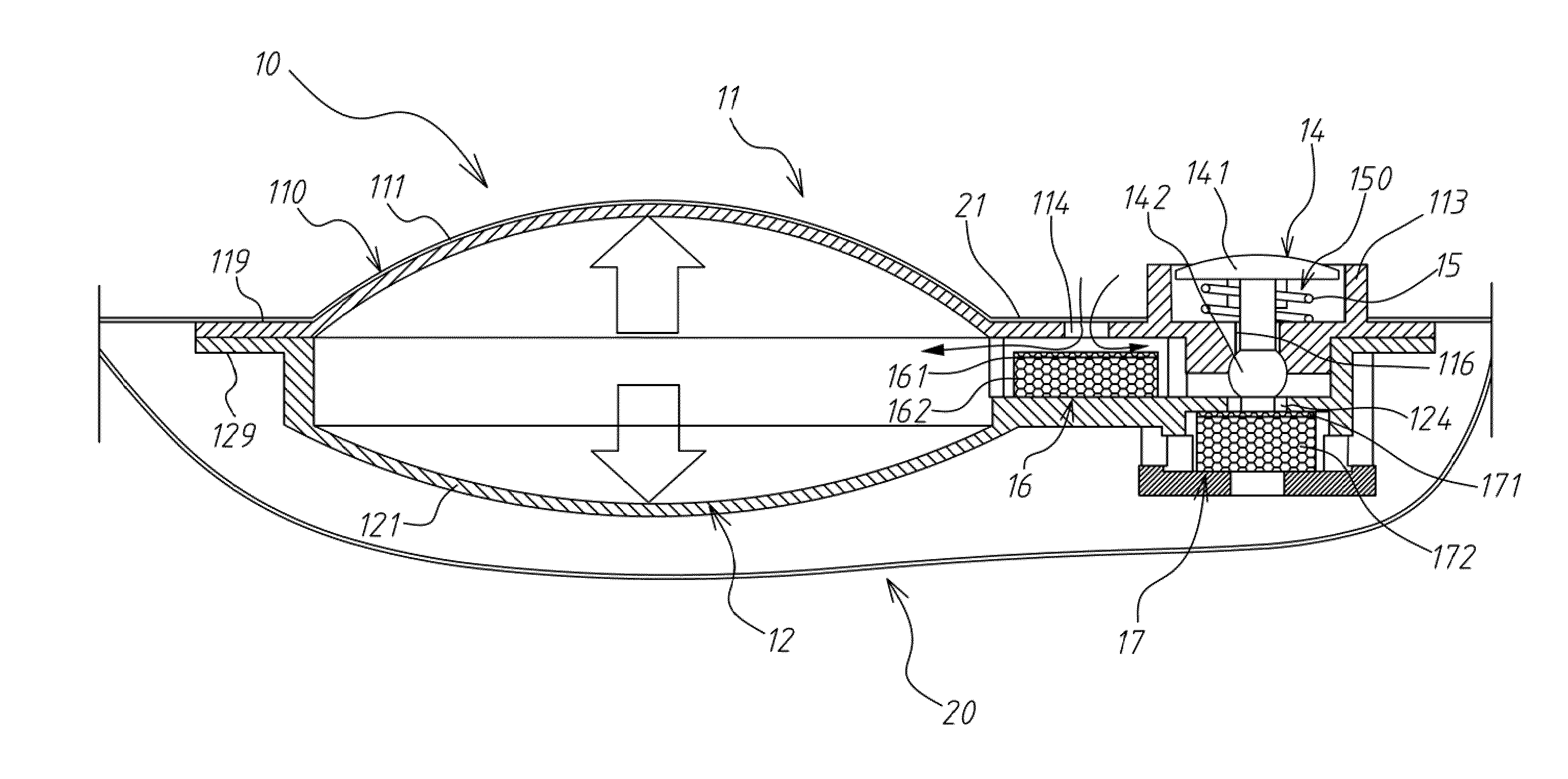
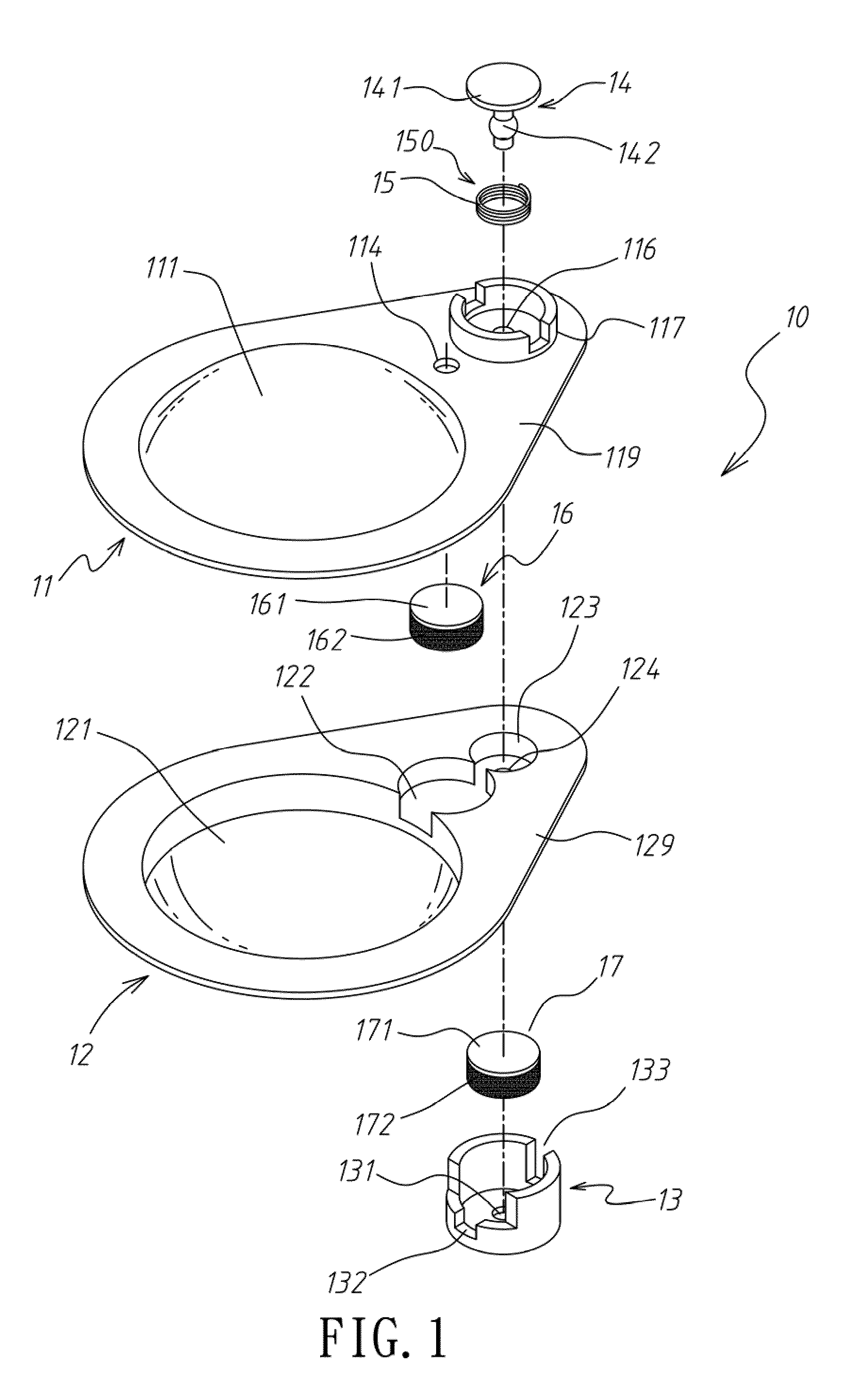
[0016]Please refer to FIGS. 1, 2 and 3, in which an inflating and deflating device 10 according to the present invention is shown. The inflating and deflating device 10 is designed for associating with different inflatable products, such as a pad 20 as shown in FIG. 2, and includes a top cover 11, a bottom base 12, a bottom sealing cap 13, a deflating button 14, a first air locker unit 16, and a second air locker unit 17.

[0017]The top cover 11 is a thin sheet having an upward protruded first domed portion 111, and has a first upper valve cap 112 and a second upper valve cap 113 sequentially located to one side of the first domed portion 111. The first upper valve cap 112 includes an air intake 114 located on the thin sheet, and a first annular leg 115 downward extended from the thin sheet, as can be seen from FIG. 3. The second upper valve cap 113 includes an air exit aperture 116, a second annular leg 117 upward extended from the thin sheet with the air exit aperture 116 centered t...

second embodiment

[0030]The second embodiment illustrated in FIG. 7 can be manipulated in the same manner as described above with reference to FIGS. 4 to 6 to achieve the same effect.


PUM


Abstract

An inflating and deflating device for connecting to an inner face of a pad includes a top cover having a first domed portion, an air intake and an air exit aperture; a bottom base connected to a lower side of the top cover; a bottom sealing cap; a deflating button located on the top cover to openably seal the air exit aperture; and a first and a second air locker unit. The bottom base has a second domed portion, which and the first domed portion together define a substantially spherical pump body, and is provided with an air intake and exit aperture. The first and second air locker units respectively openably close the air intake and the air intake and exit aperture. The inflating and deflating device has short airflow path and is airtight, and can be used to both inflate and deflate the pad.

Description

FIELD OF THE INVENTION[0001]The present invention relates to an inflating and deflating device, and more particularly to an inflating and deflating device that is suitable for use with an inflatable breast enhancer pad to both inflate and deflate the pad without the risk of leaking.BACKGROUND OF THE INVENTION[0002]Various inflatable pads have been widely employed in people's daily life, from the large-size air cushions for use as fire and lifesaving appliances or seat cushions to the small-size inflatable breast enhancer pads. These cushions or pads are either inflated using an external device, such as an air pump that force air into the cushions or the pads, or are directly equipped with an inflating device that can be manually operated to inflate the cushions or the pad. The conventional inflatable breast enhancer pad is one example of the pads equipped with an inflating device.[0003]The inflatable breast enhancer pad is small in size but plays an important role in creating a more...

Claims


Application Information

Patent Timeline
Patent Type & Authority Patents(United States)
IPC IPC(8): A41C3/00
CPCA41C3/105F16K15/147
Inventor CHEN, YING-TZE
Owner CHEN YING TZE
Why Eureka
Try Eureka