Cable cutter with reciprocating cutting wheel for cutting flexible cable
a cutting wheel and cable cutter technology, applied in the field of cable cutters, can solve the problems of increasing difficulty, shorting of wires, and nicking of wires, and achieve the effects of reducing the difficulty of cutting flexible cables, increasing the difficulty, and improving the cutting accuracy
- Summary
- Abstract
- Description
- Claims
- Application Information
AI Technical Summary
Benefits of technology
Problems solved by technology
Method used
Image
Examples
first embodiment
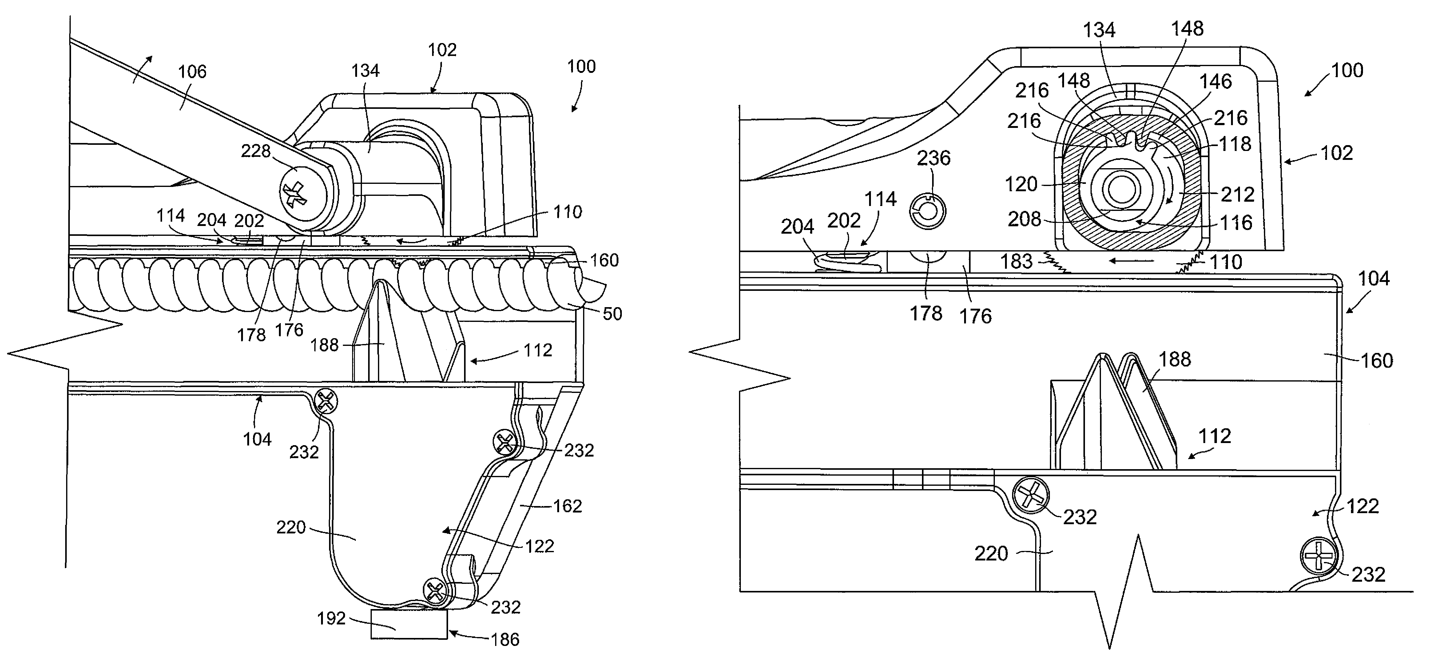
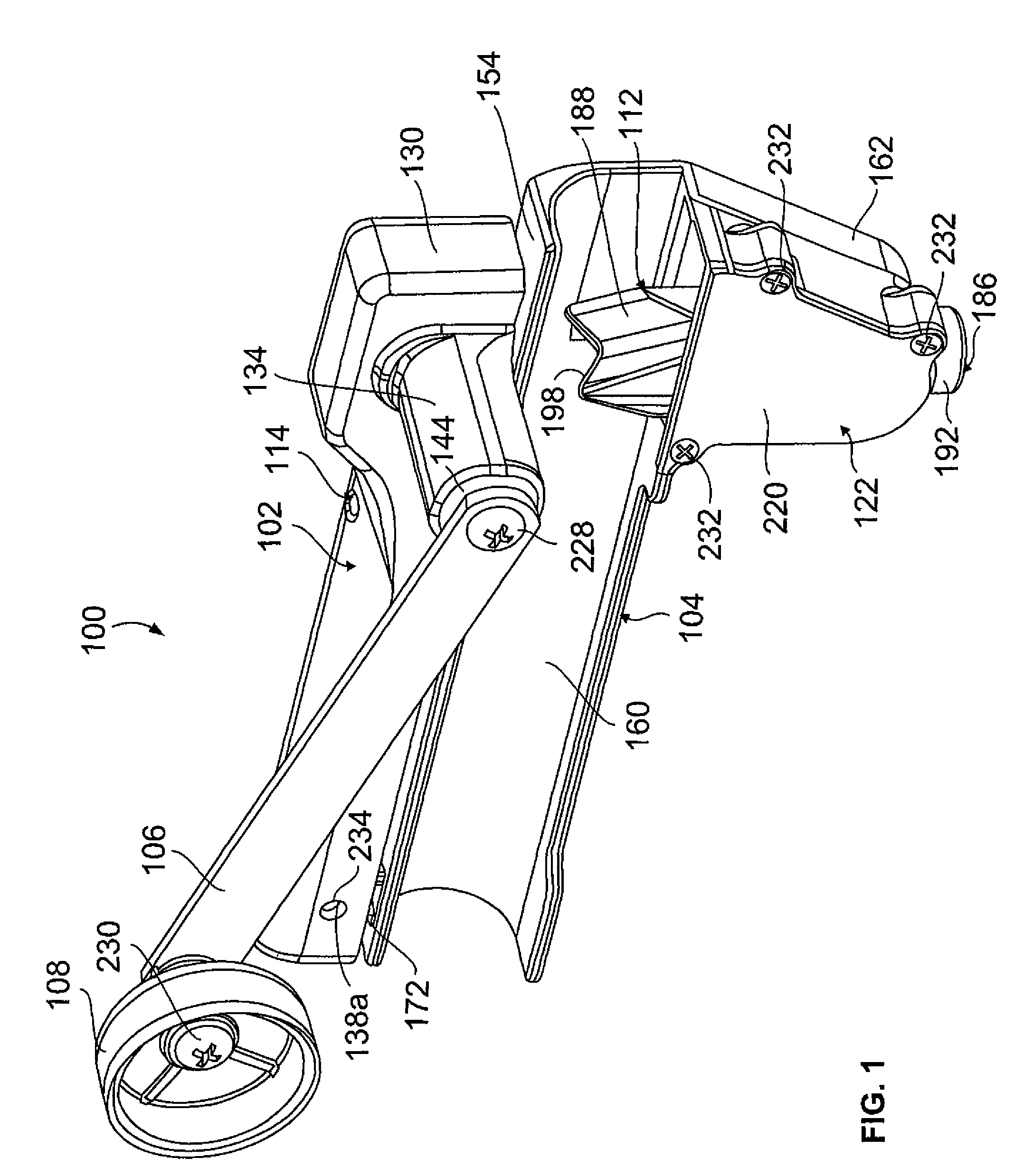
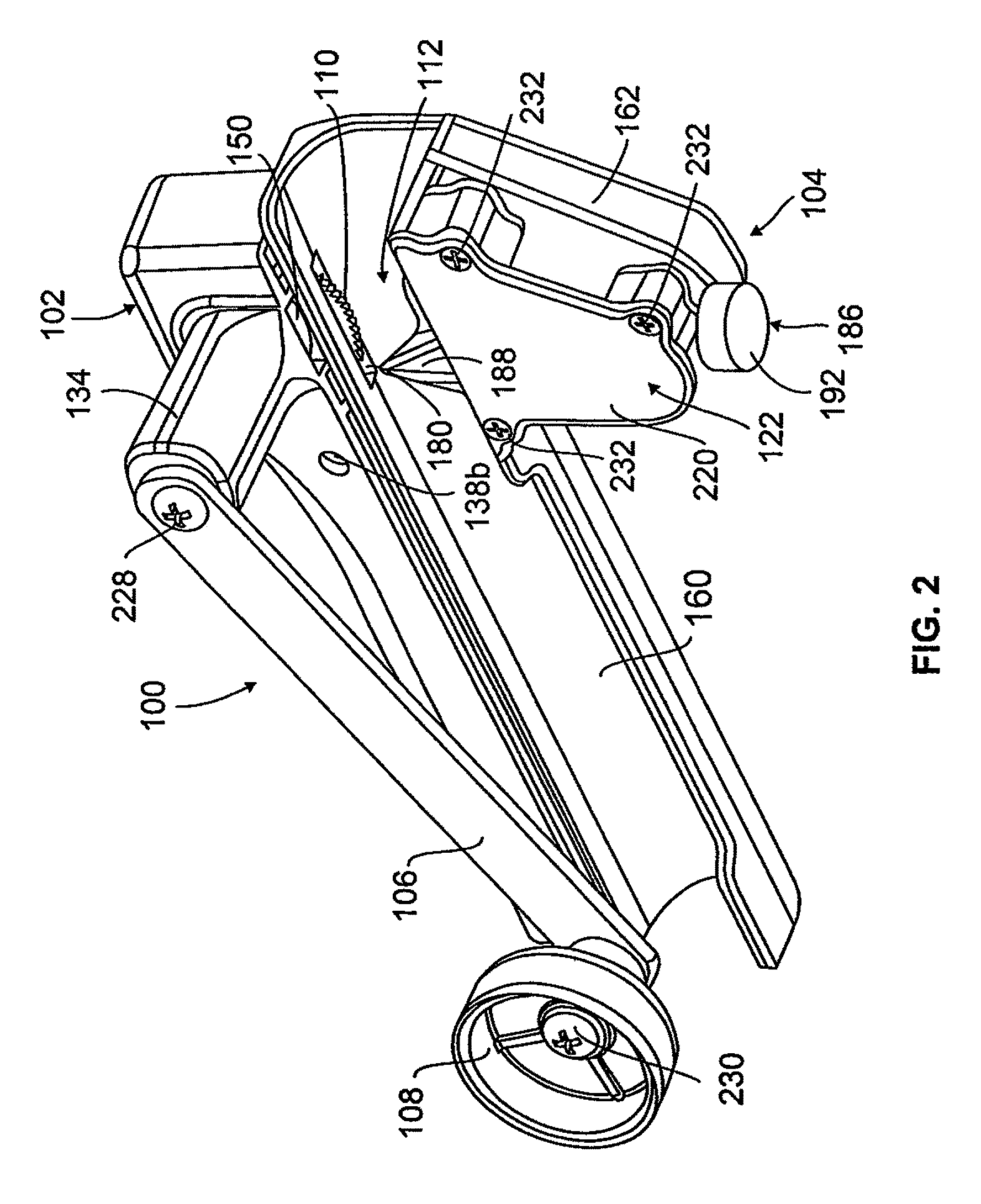
[0036]Attention is invited to FIGS. 1-20 illustrating the cable cutter 100. The cable cutter 100 includes a top frame member 102, a bottom frame member 104, a rotating handle 106, a cutting wheel 110, a clamping mechanism 112, a depth adjustment mechanism 114, a shaft 116, a cam member 118, a bushing 120, and a cover plate 122. The specifics of the structures of the individual components will be described first, and then a description of how all of the components are fit together is provided.
[0037]The top frame member 102 is best illustrated in FIG. 3. The top frame member 102 is preferably made of cast aluminum as this a cost-effective way to make frame members that have the proper amount of rigidity and strength to handle the cutting forces of the cable cutter 100, as well as wear and tear in the field. The top frame member 102 has first and second sidewalls 126, 128 which extend downwardly from opposite sides of an upper wall 124 such that an opening 136 is defined between the up...
second embodiment
[0073]Attention is invited to FIG. 21 and the cable cutter 300 which incorporates the features of the invention. The cable cutter 300 is identical to the cable cutter 100, except as described herein and as illustrated in FIG. 21. In cable cutter 300, the guide housing 134 is not provided with the elongated teeth 148 that extend into the slot 146. The slot 146 also does not extend all the way to the free end 144 of the guide housing 134, but rather is recessed back from the free end 144 such that sidewalls 353 are provided, which are similar to the sidewalls 152, by the guide housing proximate to the free end 144 thereof. An enlarged cavity or pocket 351 is provided between the sidewalls 353 and the slot 146. A second cam member 319 is also provided. The second cam member 319 is generally cylindrical and has a first end face (not shown) and an opposite second end face 413 that are connected by an outer circumferential cam surface 415. The cam member 319 has a hole 417 which extends t...
PUM
| Property | Measurement | Unit |
|---|---|---|
| rotation | aaaaa | aaaaa |
| diameters | aaaaa | aaaaa |
| rotation | aaaaa | aaaaa |
Abstract
Description
Claims
Application Information
 - R&D
- Intellectual Property
- Life Sciences
- Materials
- Tech Scout
- Unparalleled Data Quality
- Higher Quality Content
- 60% Fewer Hallucinations
Browse by: Latest US Patents, China's latest patents, Technical Efficacy Thesaurus, Application Domain, Technology Topic, Popular Technical Reports.
© 2025 PatSnap. All rights reserved.Legal|Privacy policy|Modern Slavery Act Transparency Statement|Sitemap|About US| Contact US: help@patsnap.com


