Cable cutter with reciprocating cutting wheel for cutting flexible cable

a cutting wheel and cable cutter technology, applied in the field of cable cutters, can solve the problems of increasing difficulty, shorting of wires, and nicking of wires, and achieve the effects of reducing the difficulty of cutting flexible cables, increasing the difficulty, and improving the cutting accuracy

Active Publication Date: 2008-12-11
GREENLEE TEXTRON
View PDF22 Cites 4 Cited by
  • Summary
  • Abstract
  • Description
  • Claims
  • Application Information

AI Technical Summary

Benefits of technology

[0006]The present invention provides a cable cutter that has a frame member, a shaft member, a cutting wheel and a cam member. The shaft member is rotatable about an axis. The cutting wheel is coupled to the shaft member such that rotation of the shaft member about its axis causes rotation of the cutting wheel about the shaft member's axis. The cam member is positioned around the shaft member such that the

Problems solved by technology

One of the challenges of cutting BX cable is that the blade must penetrate deep enough to cut the metallic shielding, but must not cut so deep that the insulation of the wires becomes nicked, as this could lead to a shorting of the wiring.
This challenge has increased as the amount of space provided between the metallic shi

Method used


Image

  • Cable cutter with reciprocating cutting wheel for cutting flexible cable
  • Cable cutter with reciprocating cutting wheel for cutting flexible cable
  • Cable cutter with reciprocating cutting wheel for cutting flexible cable

Examples


first embodiment

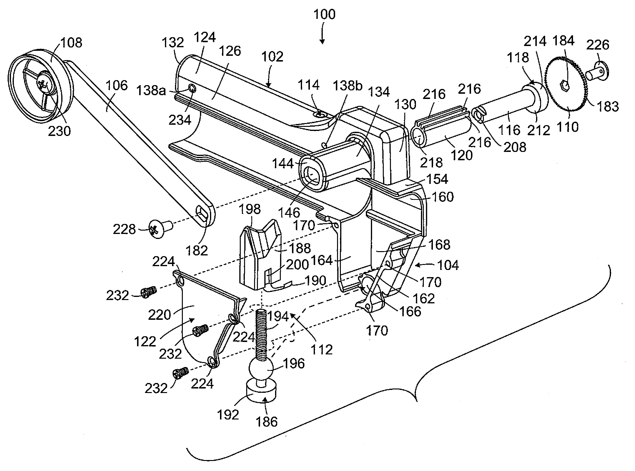
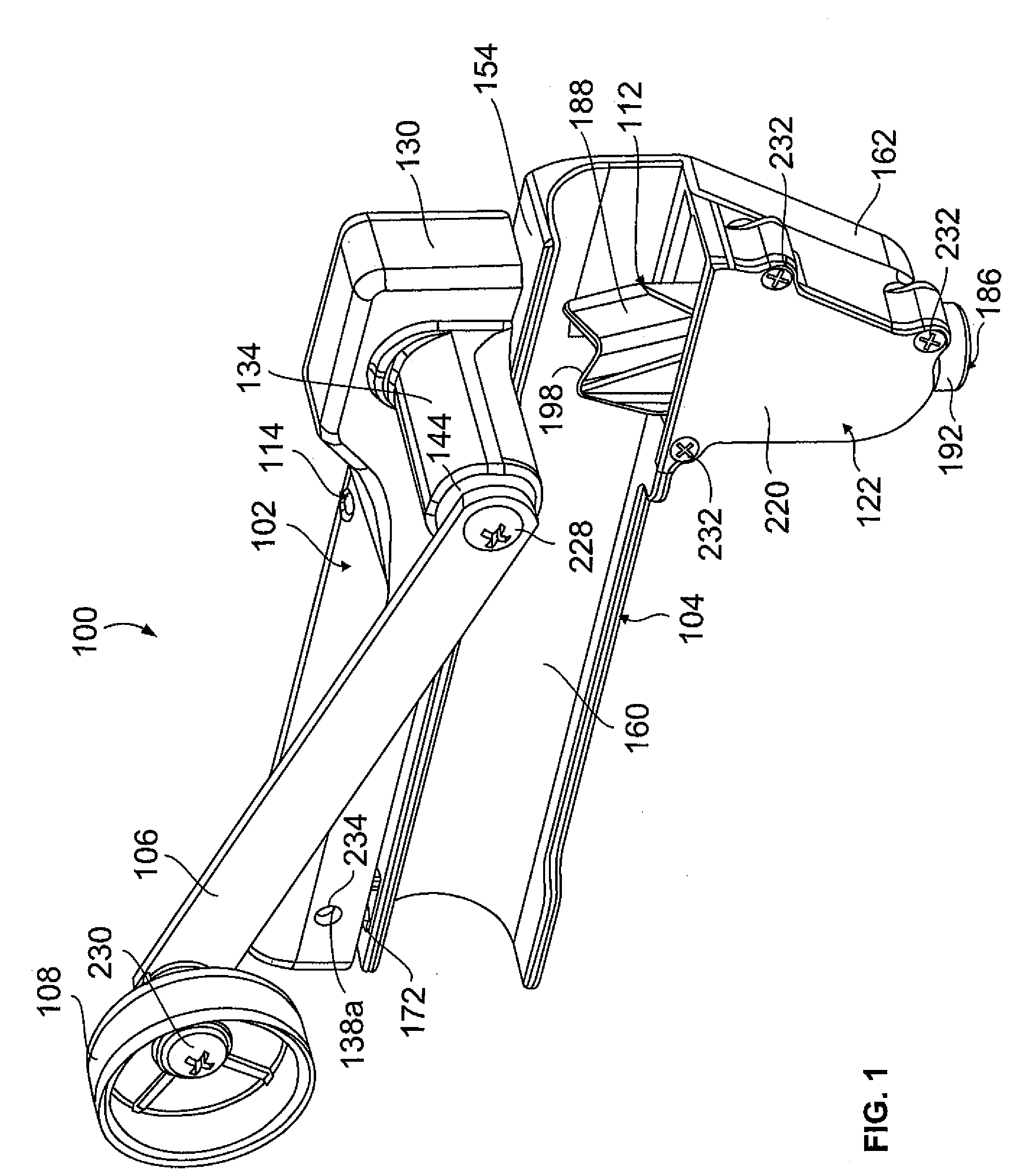
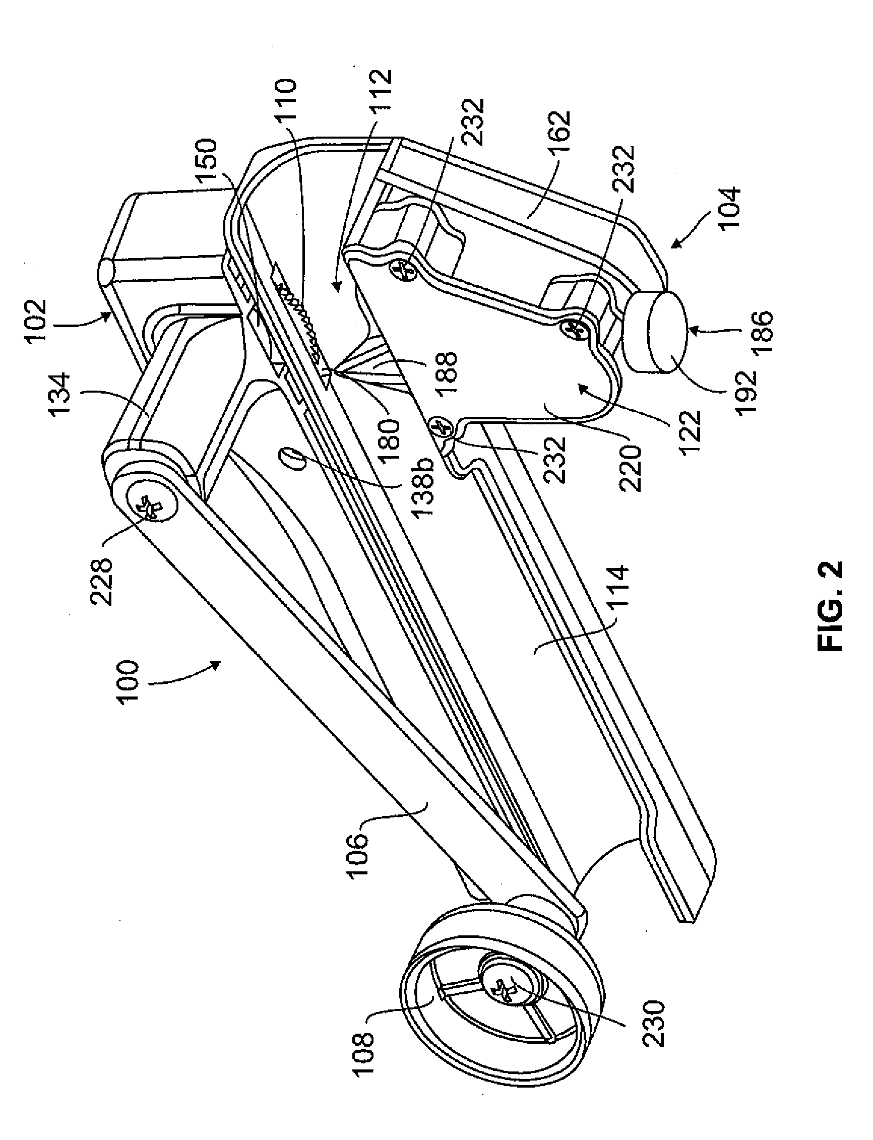
[0036]Attention is invited to FIGS. 1-20 illustrating the cable cutter 100. The cable cutter 100 includes a top frame member 102, a bottom frame member 104, a rotating handle 106, a cutting wheel 110, a clamping mechanism 112, a depth adjustment mechanism 114, a shaft 116, a cam member 118, a bushing 120, and a cover plate 122. The specifics of the structures of the individual components will be described first, and then a description of how all of the components are fit together is provided.

[0037]The top frame member 102 is best illustrated in FIG. 3. The top frame member 102 is preferably made of cast aluminum as this a cost-effective way to make frame members that have the proper amount of rigidity and strength to handle the cutting forces of the cable cutter 100, as well as wear and tear in the field. The top frame member 102 has first and second sidewalls 126, 128 which extend downwardly from opposite sides of an upper wall 124 such that an opening 136 is defined between the up...

second embodiment

[0073]Attention is invited to FIG. 21 and the cable cutter 300 which incorporates the features of the invention. The cable cutter 300 is identical to the cable cutter 100, except as described herein and as illustrated in FIG. 21. In cable cutter 300, the guide housing 134 is not provided with the elongated teeth 148 that extend into the slot 146. The slot 146 also does not extend all the way to the free end 144 of the guide housing 134, but rather is recessed back from the free end 144 such that sidewalls 353 are provided, which are similar to the sidewalls 152, by the guide housing proximate to the free end 144 thereof. An enlarged cavity or pocket 351 is provided between the sidewalls 353 and the slot 146. A second cam member 319 is also provided. The second cam member 319 is generally cylindrical and has a first end face (not shown) and an opposite second end face 413 that are connected by an outer circumferential cam surface 415. The cam member 319 has a hole 417 which extends t...


PUM


Abstract

A cutting tool includes a frame, a shaft, a cutter and a cam. The shaft is rotatable about an axis. The cutter is coupled to the shaft such that rotation of the shaft about its axis causes rotation of the cutter about the shaft's axis. The cam is positioned around the shaft such that the cam contacts the frame upon rotation of the shaft. The cam has a cam surface which is distanced away from the axis of the shaft a varying amount such that contact of the cam with the frame upon rotation of the shaft causes the shaft, and thus the cutter, to reciprocate in a generally transverse direction relative to the axis of the shaft.

Description

CROSS-REFERENCE AND INCORPORATION BY REFERENCE[0001]This application claims the domestic priority of U.S. Provisional Application Ser. No. 60 / 942,255, filed on Jun. 6, 2007, and entitled “Flexible Cable Cutter With Reciprocating Cutting Wheel”. U.S. Provisional Application Ser. No. 60 / 942,255 is hereby incorporated by reference in its entirety.FIELD OF THE INVENTION[0002]The invention generally relates to cable cutters. More particularly, the invention relates to a cable cutter having a reciprocating cutting wheel for cutting flexible cable.BACKGROUND OF THE INVENTION[0003]Flexible cable is routinely used by electricians to route electrical wiring from one place to another. One popular kind of flexible cable is called basic armored cable or BX, and is made of metal which surrounds wires. This type of cable allows an electrician to snake wires in a multitude of paths without having to spend the time necessary to bend conduit. Hence, BX cable provides protection for wiring that is con...

Claims


Application Information

Patent Timeline
IPC IPC(8): B26B13/00
CPCH02G1/1212
Inventor HARGER, JAMES ROBERT
Owner GREENLEE TEXTRON
Why Eureka
Try Eureka