
Golf ball dimple profile

a dimple profile and golf ball technology, applied in the field of golf balls, can solve the problems of cumbersome mathematical descriptions, uneven continuous dimple profiles, and ineffective coverage of tiny dimples

Active Publication Date: 2012-03-20
ACUSHNET CO
View PDF8 Cites 20 Cited by
  • Summary
  • Abstract
  • Description
  • Claims
  • Application Information

AI Technical Summary

Benefits of technology

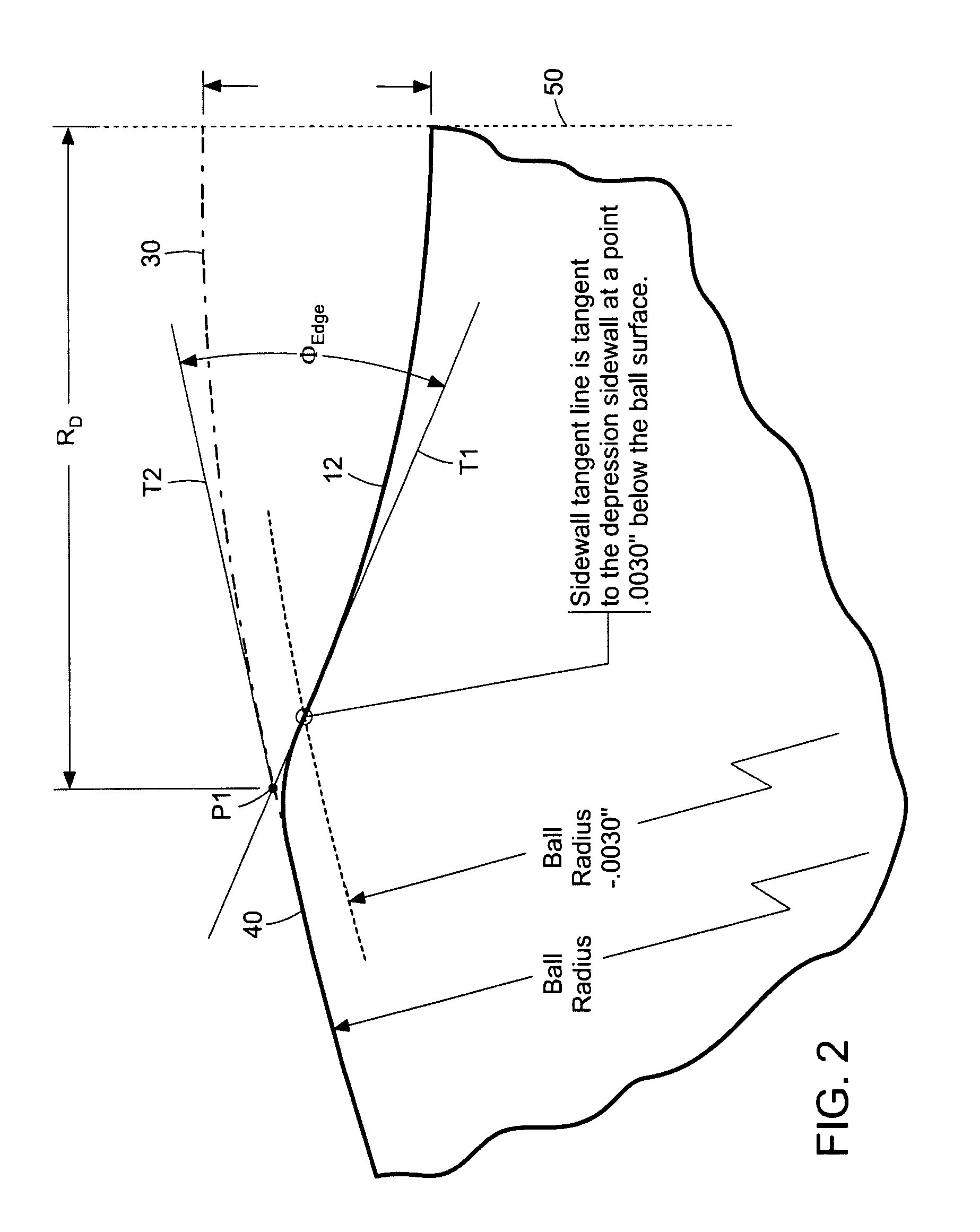
The present invention is directed to a new golf ball dimple design that has a conical edge and a spherical cap with a defined point of tangency. The dimple has a shape that is defined by a ratio called the saucer ratio and an angle called the edge angle. The difference between the slope of the conical edge and the slope of the spherical cap is less than about 2 degrees. The new design of the dimple can improve the performance of the golf ball.

Problems solved by technology

This is the primary source of drag for a golf ball.
Dimple coverage gained by filling spaces with tiny dimples is not very effective, since tiny dimples are not good turbulence generators.
With the exception of catenary profiles, the mathematical descriptions are cumbersome or do not result in smooth continuous dimple profiles.

Method used


Image

  • Golf ball dimple profile
  • Golf ball dimple profile
  • Golf ball dimple profile

Examples


Embodiment Construction

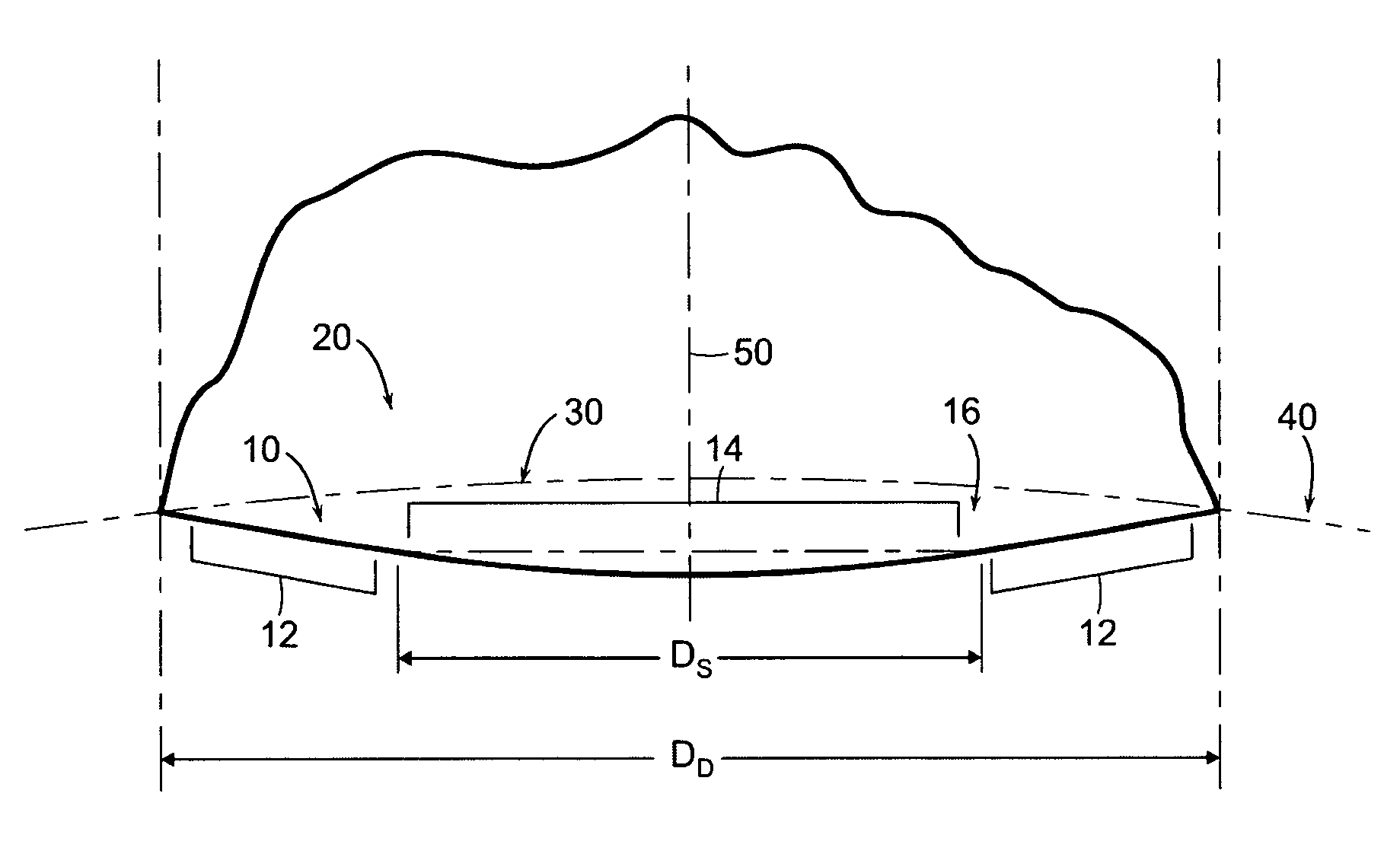
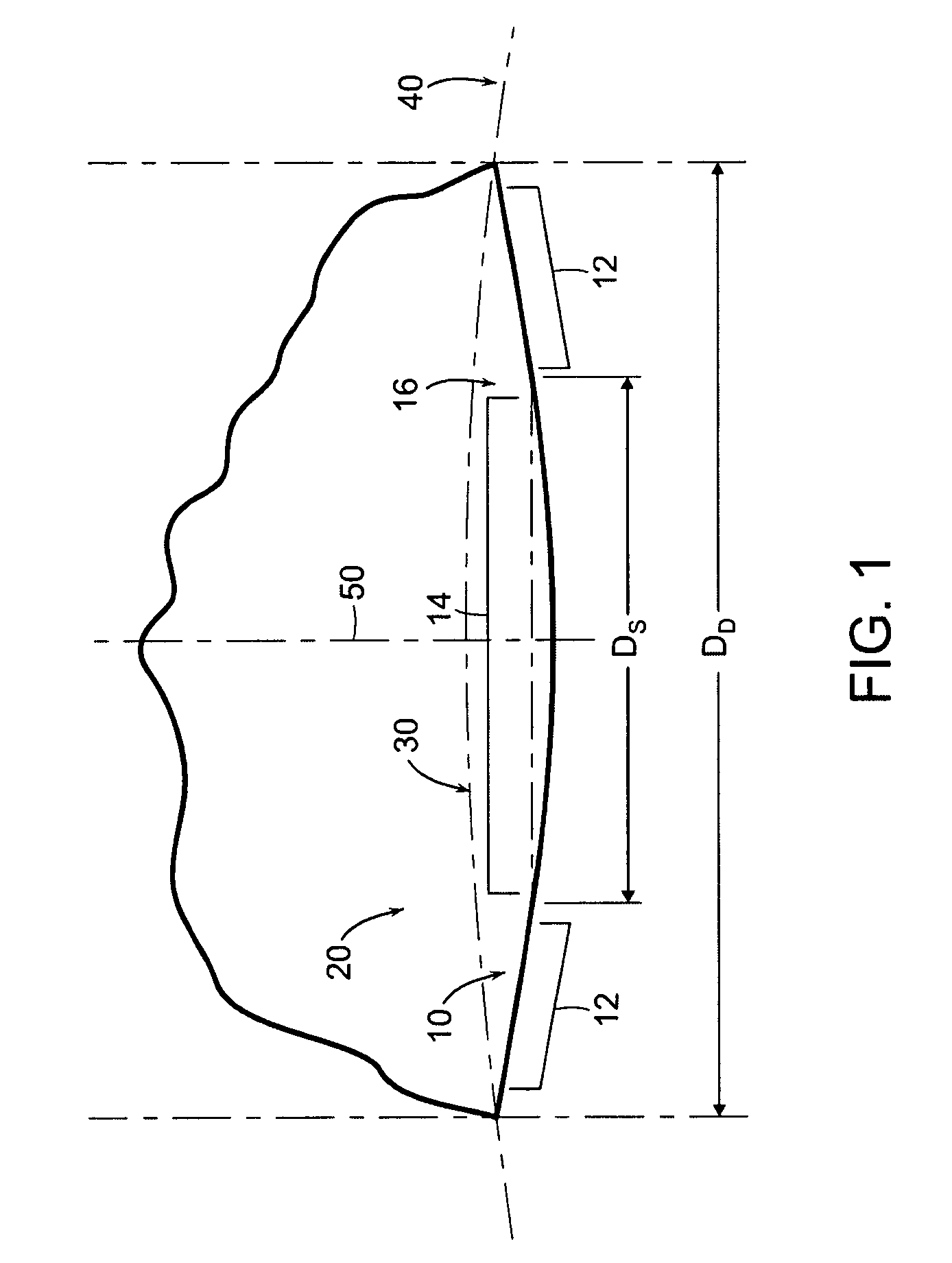
[0019]The present invention concerns a golf ball with dimples having a cross-sectional profile comprising a conical base shape and a spherical cap with a prescribed point of tangency to the cone sidewall. More particularly, the conical profiles of the present invention are defined by three parameters: dimple diameter (DD), edge angle (ΦEDGE), and saucer ratio (Sr) which is a measure of the relative curvature of the dimple bottom. These parameters fully define the dimple shape and allow for greater flexibility in constructing a dimple profile versus conventional spherical dimples. Further, conical dimples provide a unique dimple cross-section which is visually distinct.

[0020]FIG. 1 is a cross-sectional view illustrating a dimple 10 on a golf ball 20 having an outer spherical surface with a phantom portion 30 and an undimpled land area 40. A rotational axis 50 vertically traverses the center of dimple 10. The dimple 10 comprises a top conical edge 12 (an edge with no radius) and a bot...


PUM


Abstract

The present invention concerns a golf ball with dimples having a cross-sectional profile comprising a conical base shape and a spherical cap with a prescribed point of tangency to the cone sidewall. More particularly, the conical profiles of the present invention are defined by three independent parameters: dimple diameter (DD), edge angle (ΦEDGE), and saucer ratio (Sr) which is a measure of the relative curvature of the dimple bottom. These parameters fully define the dimple shape and allow for greater flexibility in constructing a dimple profile versus conventional spherical dimples. Further, conical dimples provide a unique dimple cross-section which is visually distinct.

Description

FIELD OF THE INVENTION[0001]The present invention relates to a golf ball, and more particularly, to the cross-sectional profile of dimples on the surface of a golf ball.BACKGROUND OF THE INVENTION[0002]Golf balls were originally made with smooth outer surfaces. In the late nineteenth century, players observed that the guttie golf balls traveled further as they got older and more gouged up. The players then began to roughen the surface of new golf balls with a hammer to increase flight distance. Manufacturers soon caught on and began molding non-smooth outer surfaces on golf balls.[0003]By the mid 1900's, almost every golf ball being made had 336 dimples arranged in an octahedral pattern. Generally, these balls had about 60 percent of their outer surface covered by dimples. Over time, improvements in ball performance were developed by utilizing different dimple patterns. In 1983, for instance, Titleist introduced the TITLEIST 384, which had 384 dimples that were arranged in an icosah...

Claims


Application Information

Patent Timeline
Patent Type & Authority Patents(United States)
IPC IPC(8): A63B37/12
CPCA63B37/0004A63B37/0012A63B37/0016A63B37/0019A63B37/002
Inventor MADSON, MICHAEL R.NARDACCI, NICHOLAS M.
Owner ACUSHNET CO
Learn More