
Method and system for minimizing non-uniformities in output images using halftone correction patches

a technology of non-uniformity and output image, which is applied in the field of method and system for minimizing non-uniformities in output image using halftone correction patches, can solve the problems of output image streaks and non-uniformities, spatial position errors, errors or non-uniformities still present, etc., and achieve the effect of minimizing cross-process direction non-uniformities

Active Publication Date: 2012-04-03
XEROX CORP
View PDF4 Cites 4 Cited by
  • Summary
  • Abstract
  • Description
  • Claims
  • Application Information

AI Technical Summary

Benefits of technology

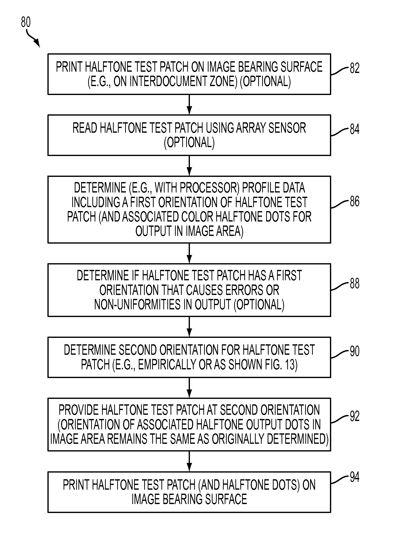
The patent text describes a method and apparatus for minimizing non-uniformities in printed documents caused by the process of printing. The method involves generating halftone test patches for each color in the image data, determining the orientation of halftone dots in the test patches, and producing halftone dots in the monitoring area with the same orientation as the test patches. This results in halftone dots that appear unaffected by the process of printing and reduces non-uniformities in the finished document. The apparatus includes a processor, sensors, and a printing apparatus with a photoreceptor and color marking stations. The technical effect of this patent is to improve the quality of printed documents by reducing non-uniformities caused by the printing process.

Problems solved by technology

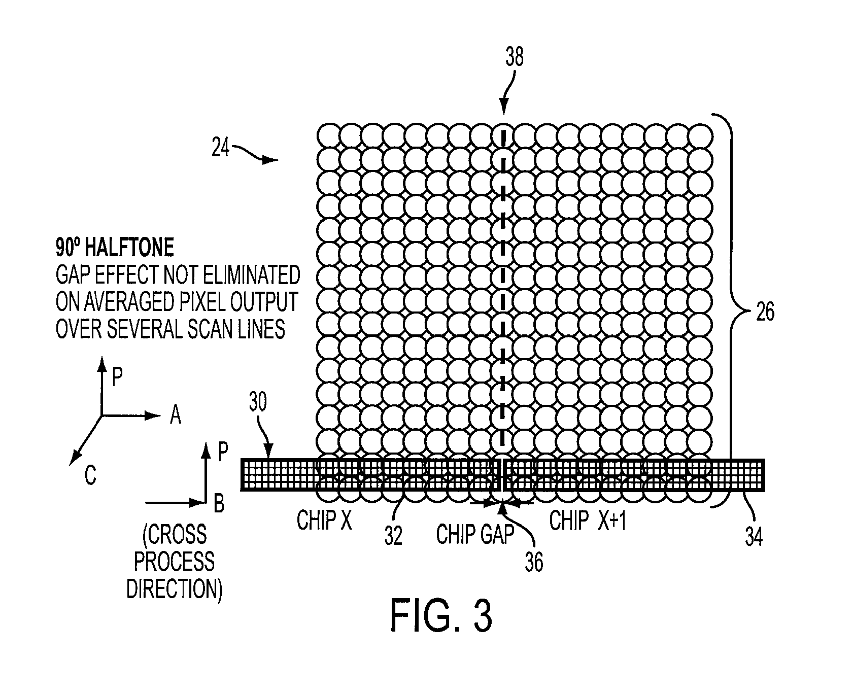
Often, however, array sensors may incorrectly sense characteristics of the test patches which can result in the production of streaks and non-uniformities in the output image.
In addition, if a multi-chip array sensor is used, as shown in FIG. 3, there may be some spatial position error.
Even with more filtering, errors or non-uniformities are still present in the output image.

Method used


Image

  • Method and system for minimizing non-uniformities in output images using halftone correction patches
  • Method and system for minimizing non-uniformities in output images using halftone correction patches
  • Method and system for minimizing non-uniformities in output images using halftone correction patches

Examples


Embodiment Construction

)

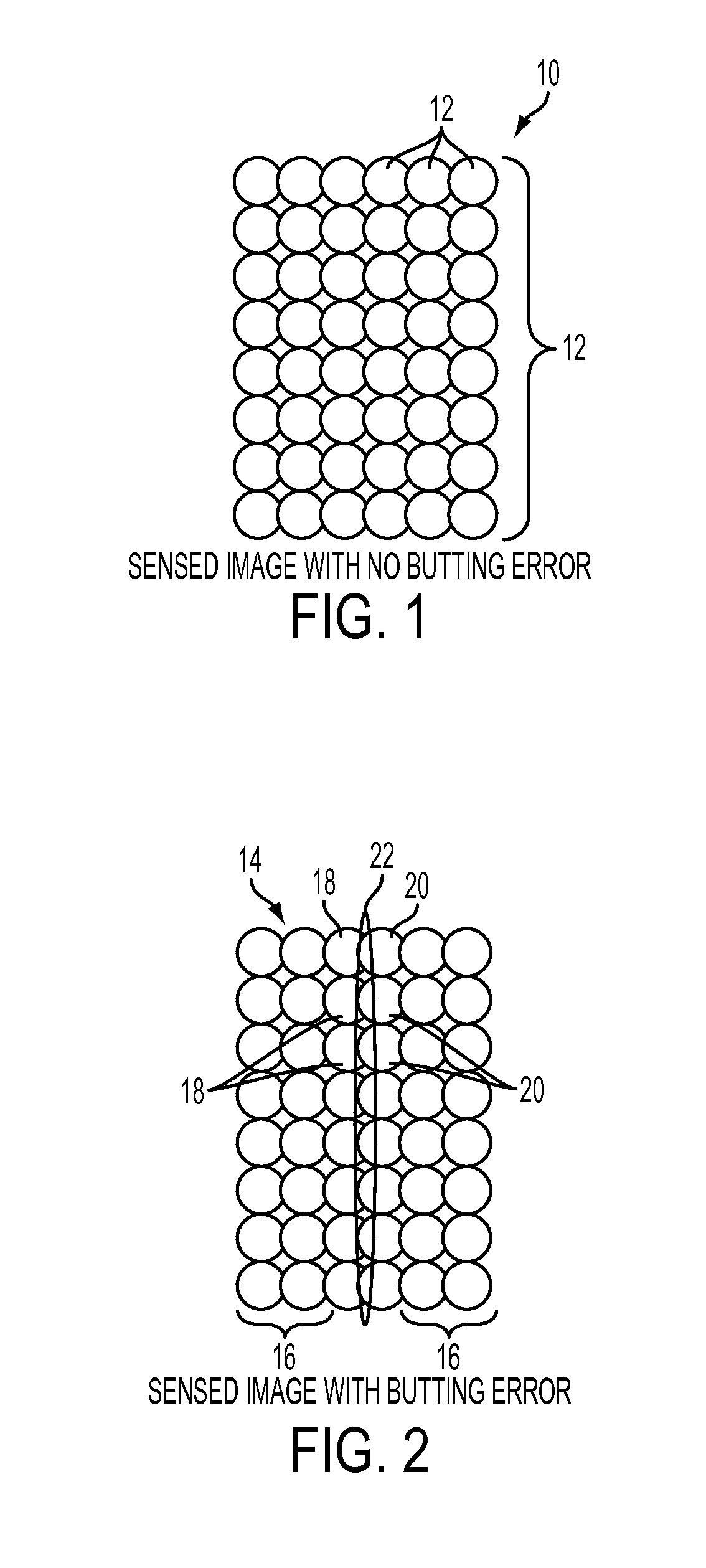
[0034]When printing color images using halftones, an output image that has uniform output is desirable. For example, FIG. 1 illustrates a detailed view of a part of an output image 10 generated by an electronic printing apparatus comprising a plurality of halftone dots 12 printed in a uniform manner and having no butting error or non-uniformities. Such uniform dots 12 will appear as a single color (or an alternate color if overlapped with one or more other colors) to the human eye on a printed document. Each color that is output may be printed at a different angle or orientation with respect to the other colors (and possibly overlay each other) which is not visible to the human eye. For example, cyan (C), magenta (M), and yellow (Y) dots may be oriented at 30, 50, and 70 degrees, respectively, and black (K) dots may be oriented at 0 or 90 degrees in an image for output. The printing and overlay of each color at a different orientation is known to produce better quality output image...


PUM


Abstract

Disclosed herein are a method and a printing apparatus implementing the method to minimize cross-process direction non-uniformities of color images in printed documents. When printing images on a photoreceptor, halftone test patches are generated for each color. A first halftone cell orientation (of dots) of the test patches and their corresponding color image data is determined. The halftone cells of test patches may be provided or rotated to a second orientation (or angle or degrees) for printing in an inter-document zone of the photoreceptor, while the first orientation of the color image data in the document image area of the photoreceptor remains the same. Errors or non-uniformities (e.g., with TRC correction) caused by sensor misreading of test patches at specific orientations in the cross-process direction are substantially eliminated, thereby providing output images without streaks or visible errors.

Description

BACKGROUND[0001]1. Field[0002]The present disclosure is generally related to minimizing cross-process direction non-uniformities of output images in printed documents caused by sensor misreadings using halftone patches.[0003]2. Description of Related Art[0004]An array sensor may be used in a printing device to scan images for output and thereby measure a wide variety of image defects that might occur in the xerographic or raster process. For example, as known in the art, the array sensor may scan a photoreceptor (e.g., in the form of a belt) to determine if toner is properly dispersed for output. The array sensor may be used to detect both non-uniformities in the cross-process direction and process direction (i.e., streaks and bands, respectively) for marking technologies. “Streaks” as used herein are defined as uniformity variations in the cross-process direction, at all spatial frequencies (i.e., “narrow” streaks as well as “wide” streaks including variations along the lateral sid...

Claims


Application Information

Patent Timeline
Patent Type & Authority Patents(United States)
IPC IPC(8): G03G15/00G03G15/08
CPCH04N1/4058H04N1/58H04N1/6033G03G15/5041
Inventor HOSIER, PAUL A.
Owner XEROX CORP
Learn More