Multipositional vault door

a vault door and multi-position technology, applied in the field of vault doors, can solve the problem that nonetheless does not provide a door with discrete opening orientations

Inactive Publication Date: 2012-05-01
U S F FABTION
View PDF13 Cites 14 Cited by
  • Summary
  • Abstract
  • Description
  • Claims
  • Application Information

AI Technical Summary

Problems solved by technology

Although Schack addresses issues associated with the weight of the door via torsion bars, it nonetheless does not provide a door with discrete opened orientations.

Method used


Image

  • Multipositional vault door
  • Multipositional vault door
  • Multipositional vault door

Examples


Embodiment Construction

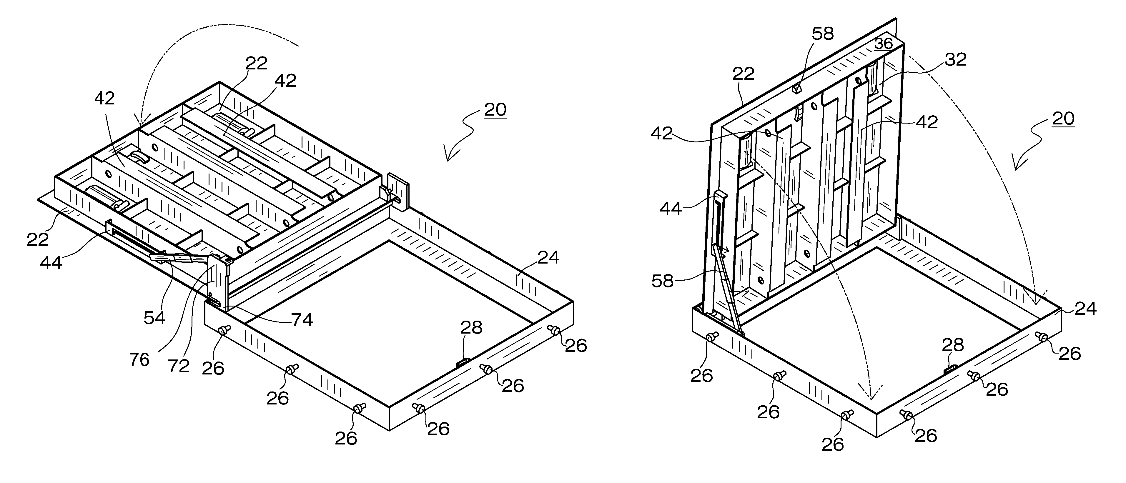
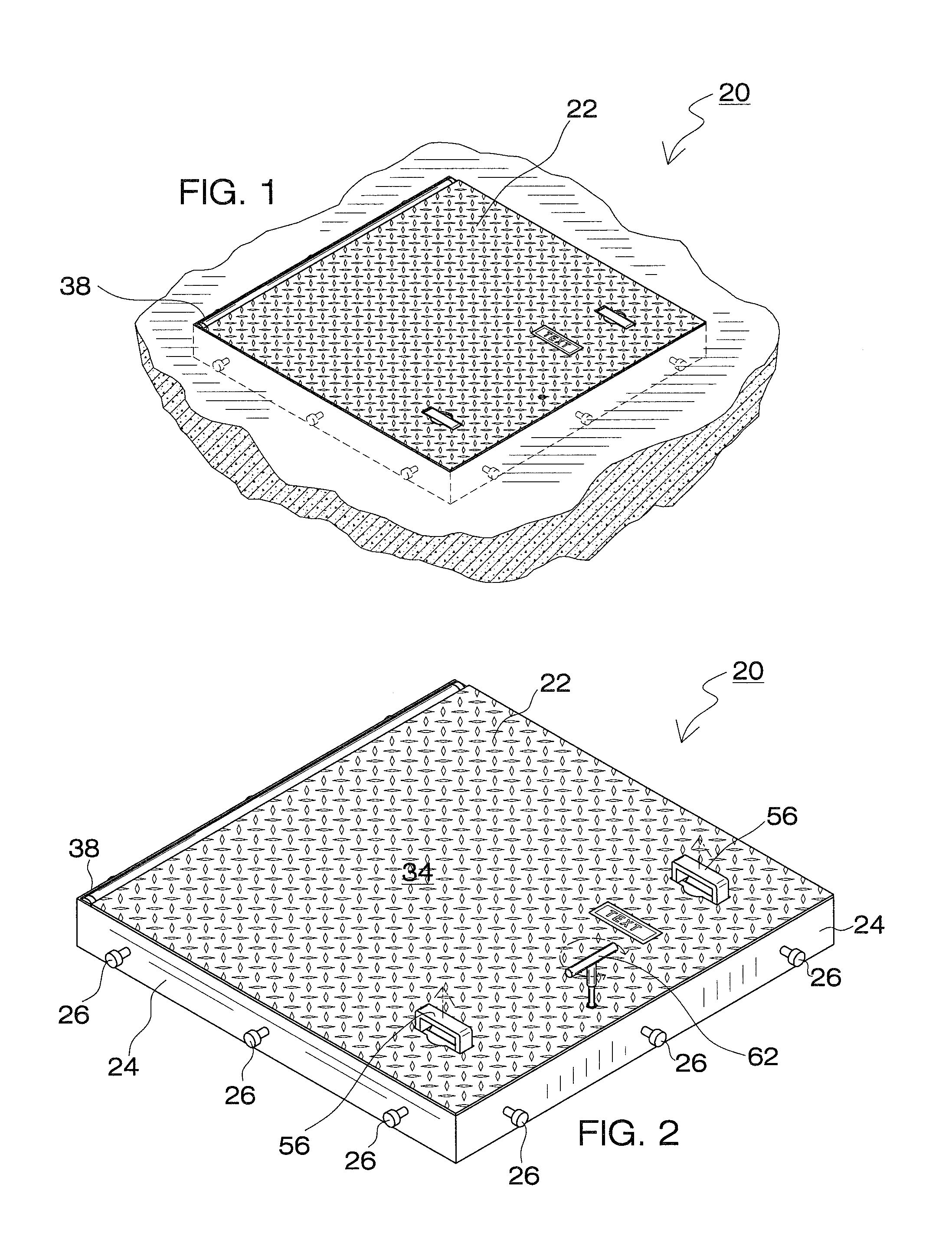
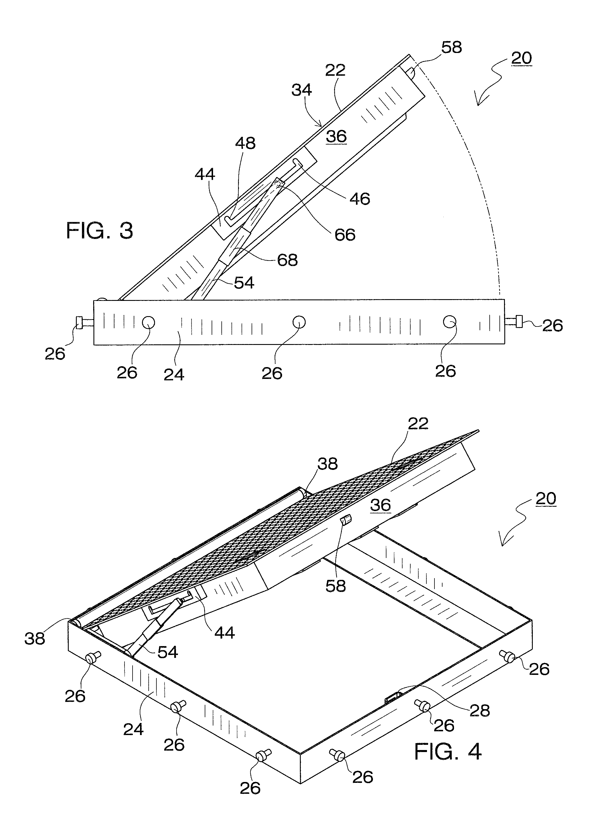
[0022]The present invention relates to a vault door mechanism that assists a user in opening or closing the door. A hold-open arm and hinge plate pivotally interconnect the door to a surrounding frame and are fixed in place by an associated locking mechanism. The locking mechanism stops the door in the partially opened position prior to being fully opened or closed, thereby assisting the user in handling the door. The details of the present invention, and the manner in which they interrelate, will be described in greater detail hereinafter.

[0023]With reference to FIGS. 1 and 2, the closure 20 of the present invention is depicted. Closure 20 comprises a vault door 22 and a surrounding frame 24. In the depicted embodiment, both frame 24 and door 22 have a rectangular shape, although those of ordinary skill in the art will readily appreciate other configurations. Frame 24 is defined by both inner and outer peripheral extents and is designed to be ground mounted so as to an access openi...


PUM


Abstract

The present invention relates to a vault door mechanism that assists a user in opening or closing the door. A hold-open arm and hinge plate pivotally interconnect the door to a surrounding frame and are fixed in place by an associated locking mechanism. The locking mechanism stops the door in the partially opened position prior to being fully opened or closed, thereby assisting the user in handling the door. The details of the present invention, and the manner in which they interrelate, will be described in greater detail hereinafter.

Description

FIELD OF THE INVENTION[0001]This invention relates to vault door. More particularly, the present invention relates to a vault door that is selectively positionable between closed, partially opened, and fully opened orientations.DESCRIPTION OF THE BACKGROUND ART[0002]The use of access doors in known in the prior art. These doors are often mounted within the ground and control access to underground utilities. Access doors have to be strong enough to prevent unauthorized access as well as to withstand vehicle traffic. But access doors must also be light enough to permit opening by a single user. Access door must also be capable of opening wide enough to ingress of larger equipment.[0003]An example of a prior art access door is disclosed in U.S. Pat. No. 4,133,074 to Schack. Schack discloses a spring assisted door construction. The door of Schack includes both closed, raised, and fully open positions. A first pair of torsion rods are arranged to be loaded when the door is swung down to ...

Claims


Application Information

Patent Timeline
Patent Type & Authority Patents(United States)
IPC IPC(8): E05F1/10
CPCE05B65/006E05C17/24E06B5/01E05C17/32Y10T16/544Y10T16/547Y10T16/5445Y10T16/5448Y10T70/5296
Inventor SLIMAK, LOUISLOPEZ, MARVIN
Owner U S F FABTION
Why Eureka
Try Eureka