
Foldaway child booster seat

a child booster seat and foldaway technology, applied in the field of foldaway child booster seats, can solve the problems of inconvenient transportation for use on other vehicles, cumbersome storage, and cumbersome seat together with the protruding armrest, and achieve the effect of reducing the vertical thickness of the seat member

Inactive Publication Date: 2012-05-22
GLANCE PATRICK M
View PDF15 Cites 11 Cited by
  • Summary
  • Abstract
  • Description
  • Claims
  • Application Information

AI Technical Summary

Benefits of technology

"The present invention is a portable and collapsible child booster seat for a vehicle. It includes a seat member that can be attached to a vehicle seat and arm rests that extend upward from the seat member. The seat member is thinner in its collapsed position than when in the deployed position. The arm rests are collapsible to a storage position. The seat is releasibly attachable to a vehicle seat and can be easily removed for storage. The seat frame is a collapsible scissors frame that supports a raisable seat cushion in an elevated position and is collapsible upon actuation to lower the seat cushion. The arm rests on legs that pivotally attach to the chair base and the horizontal arm. The seat frame is maintained in a deployed position by a mechanical latch and is collapsible upon releasing the latch. These features and advantages of the present invention provide a convenient and easy-to-use child booster seat for vehicles."

Problems solved by technology

One of the drawbacks with a conventional child booster seat is that the seat cushion may be quite thick, perhaps four inches for a smaller child, and the thick seat together with the protruding arm rest is cumbersome and difficult to store when not in use.
The seat is also inconvenient to transport for use on other vehicles, such as when a child is invited to ride in a friend's car or the child's family rents a car while on a trip.

Method used


Image

  • Foldaway child booster seat
  • Foldaway child booster seat
  • Foldaway child booster seat

Examples


Embodiment Construction

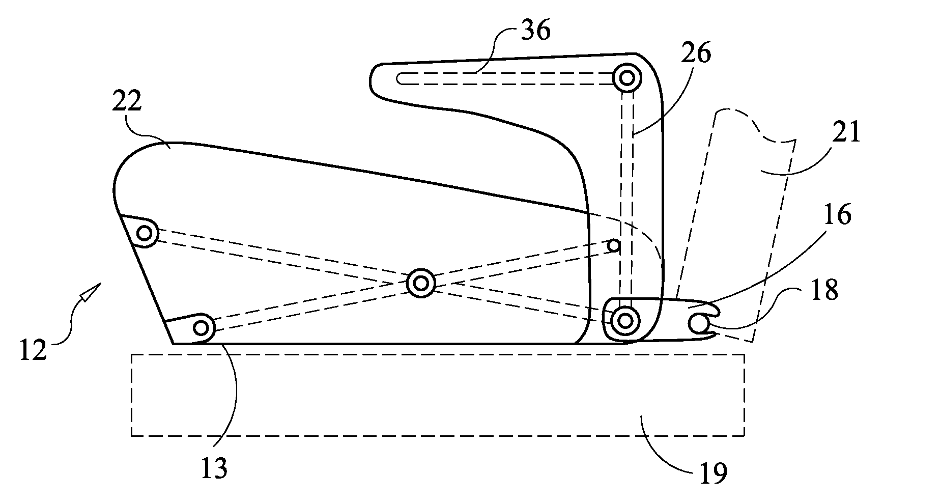
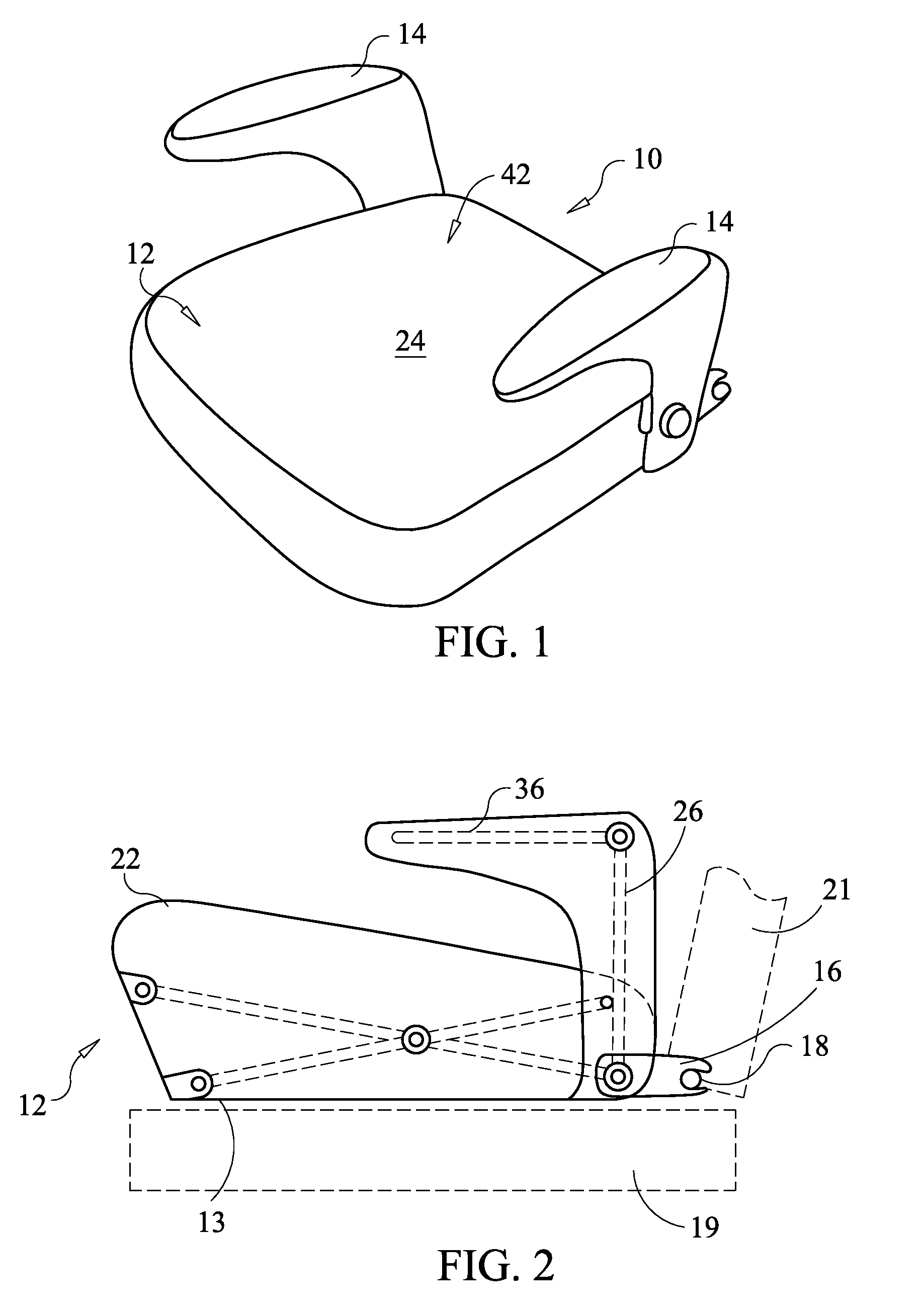
[0028]Booster seat 10 comprises a seat cushion or seat member 12 and arm rests 14 on each side of the seat member. The seat desirably includes releasable latches 16 that extend rearwardly from opposite sides of the seat member. The latches releasibly engage wire rod mounting brackets 18 that are mounted in newer automobile seats at the bight between the back 21 and seat member 19 (FIG. 2). These brackets are often standard equipment for attaching child seats to the automobile seats. Latches on child seats that engage these wires are known. These latches are called LATCH connectors and the brackets are called ISOFIX wires 18.

[0029]Seat member 12, shown in its deployed condition in FIGS. 1 and 2, comprises a bottom 13, a collapsible internal frame 20 (FIGS. 5-8) extending upwardly from the bottom, surface padding 22 mounted on the top 23 of the frame, and a cover 24 formed of fabric, plastic sheeting or other surface material covering the exterior of the seat cushion. Arm rests 14 ser...


PUM


Abstract

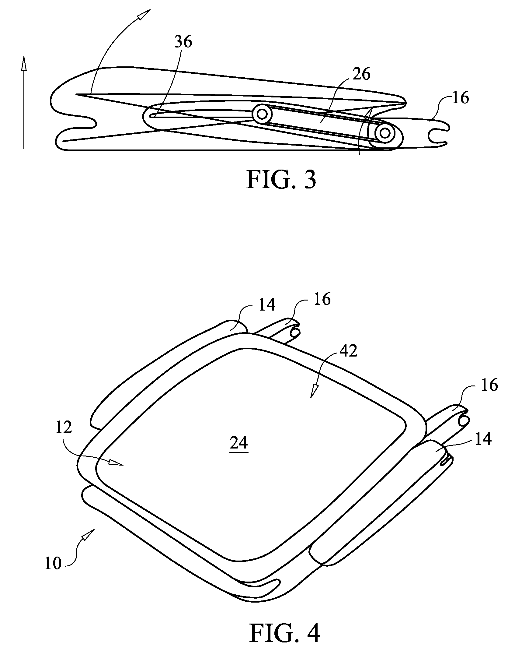
A portable, collapsible child booster seat for a vehicle comprises a collapsible seat member that removably rests on a vehicle seat with collapsible arm rests extending upwardly from opposite sides of the seat member. The seat member includes an upper seating surface supported on a collapsible scissors frame seat base. The seat base is raisable to a deployed position and collapsible to a storage position. The arm rests comprise horizontal arms pivotably mounted on raisable legs. The arm rests have a deployed position, wherein the legs extend upwardly from the seat base and the arms extend forwardly, and a collapsed position, wherein the legs and arms are in a generally horizontal position adjacent the sides of the seat base. The arm rests and seat base are operably interconnected, such that raising or lowering the arm rests between their deployed and collapsed positions causes deployment and collapse of the seat base.

Description

CROSS-REFERENCE TO RELATED APPLICATIONS[0001]This application is based in part on and claims the priority of applicant's Provisional Patent Application No. 61 / 144,637, filed Jan. 14, 2009, which is incorporated by reference.STATEMENT REGARDING FEDERALLY SPONSORED RESEARCH OR DEVELOPMENT[0002]Not Applicable.PARTIES TO A JOINT RESEARCH AGREEMENT[0003]Not Applicable.REFERENCE TO A SEQUENCE LISTING[0004]Not Applicable.BACKGROUND OF THE INVENTION[0005]Child safety seats for vehicles include their own safety belts and are generally mandated for children under four years old who weigh less than forty pounds. Child booster seats are used for larger children, typically four to eight year old children who weigh between forty and eighty pounds and are less than about 4 feet 9 inches tall.[0006]Child booster seats raise the position of these children so that the child will be in an effective position to use the vehicle's seat belt system. These seats are sometimes called belt positioning booste...

Claims


Application Information

Patent Timeline
Patent Type & Authority Patents(United States)
IPC IPC(8): A47D1/10A47D1/02
CPCB60N2/2866B60N2/2887B60N2/4606B60N2/5833B60N2002/2896B60N2/753
Inventor GLANCE, PATRICK M.
Owner GLANCE PATRICK M
Learn More