Method of estimating weighting function of audio signals in a hearing aid

a technology of audio signal and weighting function, which is applied in the direction of transducer details, electrical transducers, electrical apparatus, etc., can solve the problems of unnatural sensation for hearing aid users, difficult to obtain good sound localization and speech intelligibility, and more microphone nois

Active Publication Date: 2012-06-19
OTICON
View PDF11 Cites 27 Cited by
  • Summary
  • Abstract
  • Description
  • Claims
  • Application Information

AI Technical Summary

Benefits of technology

[0025]It is an advantage of the present invention that this decision is performed by means of providing time-frequency representations of the target signal and the noise signal so that the two directional signals can be compared with each other for each time-frequency coefficient, because thereby it can be determined for each time-frequency coefficient whether the time-frequency coefficient is related to the target signal or the noise signal, and this enables the estimation of the direction-dependent time-frequency mask. Time-frequency representations may be complex-valued fields over time and frequency, where the absolute value of the field represents “energy density” (the concentration of the root mean square over time and frequency) or amplitude, and the argument of the field represents phase. Thus the time-frequency coefficients represent the energy of the signal.
[0026]The time-frequency mask may be estimated in the hearing aid, which the user wears. Alternatively, the time-frequency mask may be estimated in a device arranged externally relative to the hearing aid and located near the hearing aid user. It is an advantage that the estimated time-frequency mask may still be used in the hearing aid even though it may be estimated in an external device, because the hearing aid and the external device may communicate with each other by means of a wired or wireless connection.
[0027]In one embodiment using the time-frequency representation of the target signal and the noise signal to estimate a time-frequency mask comprises comparing the at least two directional signals with each other for each time-frequency coefficient in the time-frequency representation.
[0028]In one embodiment using the estimated time-frequency mask to estimate the direction-dependent time-frequency gain comprises determining, based on said comparison, for each time-frequency coefficient, whether the time-frequency coefficient is related to the target signal or the noise signal.
[0030]obtaining an envelope for each time-frequency representation of the at least two directional signals;
[0031]using the envelope of the time-frequency representation of the target signal and the noise signal to estimate the time-frequency mask.

Problems solved by technology

For hearing aid users good sound localization and speech intelligibility may often be harder to obtain.
This is an unnatural sensation for the hearing aid user, because the shape of the pinna would normally only accentuate sound signals coming frontally.
A second order directionality pattern provides better directionality than a first order directionality pattern, but a disadvantage is more microphone noise.
If for instance a directional signal and an omnidirectional signal were compared, the difference between these two signals will not be as big as the difference between two directional signals, and it would therefore be more difficult to separate the target signal and the noise / interferer signal, when using an omnidirectional signal and a directional signal.
The front microphone in the hearing aid may pick up the desired audio signals from the target source, and the rear microphone in the hearing aid may pick up the undesired audio signals not coming from the target source.
However, audio signals will typically be mixed, and the problem will then be to decide what contribution to the incoming signal is made from which sources.

Method used


Image

  • Method of estimating weighting function of audio signals in a hearing aid
  • Method of estimating weighting function of audio signals in a hearing aid
  • Method of estimating weighting function of audio signals in a hearing aid

Examples


Embodiment Construction

[0099]In the following description, reference is made to the accompanying figures, which show by way of illustration how the invention may be practiced.

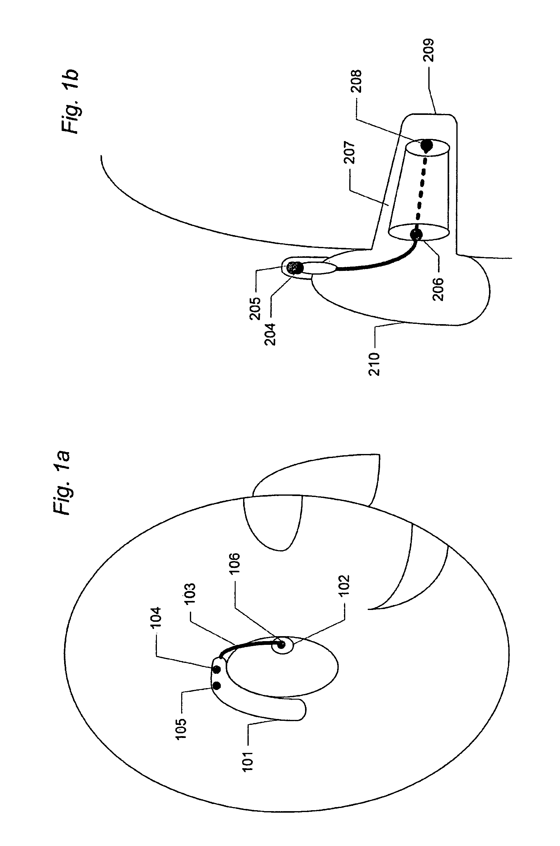
[0100]FIG. 1a shows a schematic view of a hearing aid user wearing a hearing aid with a number of input transducers, such as microphones. The hearing aid is shown to comprise a part away from the ear, such as a behind-the-ear (BTE) shell or part 101 and part near or in the ear canal, such as an in-the-ear (ITE) part 102. In the following the part near or in the ear canal will be referred to as an ITE part, but it is understood that the part arranged near or in the ear canal is not limited to an ITE part, but may be any kind of part arranged near or in the ear canal. Furthermore, in the following, the part arranged away from or behind the ear will be referred to as a BTE part, but it is understood that the part arranged away from or behind the ear is not limited to a BTE part, but it may be any kind of part arranged away from or behin...


PUM


Abstract

Disclosed is method of generating an audible signal in a hearing aid by estimating a weighting function of received audio signals, the hearing aid is adapted to be worn by a user; the method comprises the steps of:estimating a directional signal by estimating a weighted sum of two or more microphone signals from two or more microphones, where a first microphone of the two or more microphones is a front microphone, and where a second microphone of the two or more microphones is a rear microphone;estimating a direction-dependent time-frequency gain, and synthesizing an output signal;wherein estimating the direction-dependent time-frequency gain comprises:obtaining at least two directional signals each containing a time-frequency representation of a target signal and a noise signal; and where a first of the directional signals is defined as a front aiming signal, and where a second of the directional signals is defined as a rear aiming signal;using the time-frequency representation of the target signal and the noise signal to estimate a time-frequency mask; andusing the estimated time-frequency mask to estimate the direction-dependent time-frequency gain.

Description

FIELD OF THE INVENTION[0001]This invention generally relates to generating an audible signal in a hearing aid. More particularly, the invention relates to a method of estimating and applying a weighting function to audio signals.BACKGROUND OF THE INVENTION[0002]Sound signals arriving frontally at the ear are accentuated due to the shape of the pinna, which is the external portion of the ear. This effect is called directionality, and for the listener it improves the signal-to-noise ratio for sound signals arriving from the front direction compared to sound signals arriving from behind. Furthermore, the reflections from the pinna enhance the listener's ability to localize sounds. Sound localization may enhance speech intelligibility, which is important for distinguishing different sound signals such as speech signals, when sound signals from more than one direction in space are present. Localization cues used by the brain to localize sounds can be related to frequency dependent time a...

Claims


Application Information

Patent Timeline
Patent Type & Authority Patents(United States)
IPC IPC(8): H04R25/00
CPCH04R25/407H04R1/406H04R25/453H04R2225/021H04S2420/01H04R2225/0216
Inventor PEDERSEN, MICHAEL SYSKINDKJEMS, ULRIKRASMUSSEN, KARSTEN BOELMEDYB, THOMAS BOBOLDT, JESPER BUNSOW
Owner OTICON
Why Eureka
Try Eureka