Image pickup apparatus shutter control

a pickup apparatus and shutter control technology, applied in the field of shutter control technology, can solve the problems of space and cost, variable exposure period, shutter speed,

Inactive Publication Date: 2012-07-03
SONY CORP
View PDF6 Cites 4 Cited by
  • Summary
  • Abstract
  • Description
  • Claims
  • Application Information

AI Technical Summary

Benefits of technology

[0009]To overcome such problems, it is desirable to provide an image pickup apparatus that can precisely and easily control an exposure time by considering changes of movement characteristics of a rear curtain with time.
[0011]According to the present invention, it is possible to precisely and easily control an exposure period in accordance with changes with time of the biasing force of the biasing unit of the rear blade.

Problems solved by technology

Accordingly, the shutter device has a problem in which there are variations in the exposure periods (shutter speeds) in the respective positions in an image pickup area.
However, providing such a detecting unit is not advantageous from the viewpoints of space and costs.

Method used


Image

  • Image pickup apparatus shutter control
  • Image pickup apparatus shutter control
  • Image pickup apparatus shutter control

Examples


Embodiment Construction

[0029]A description will hereunder be given of an embodiment of the present invention with reference to the drawings.

[0030]1. Overview of Structure

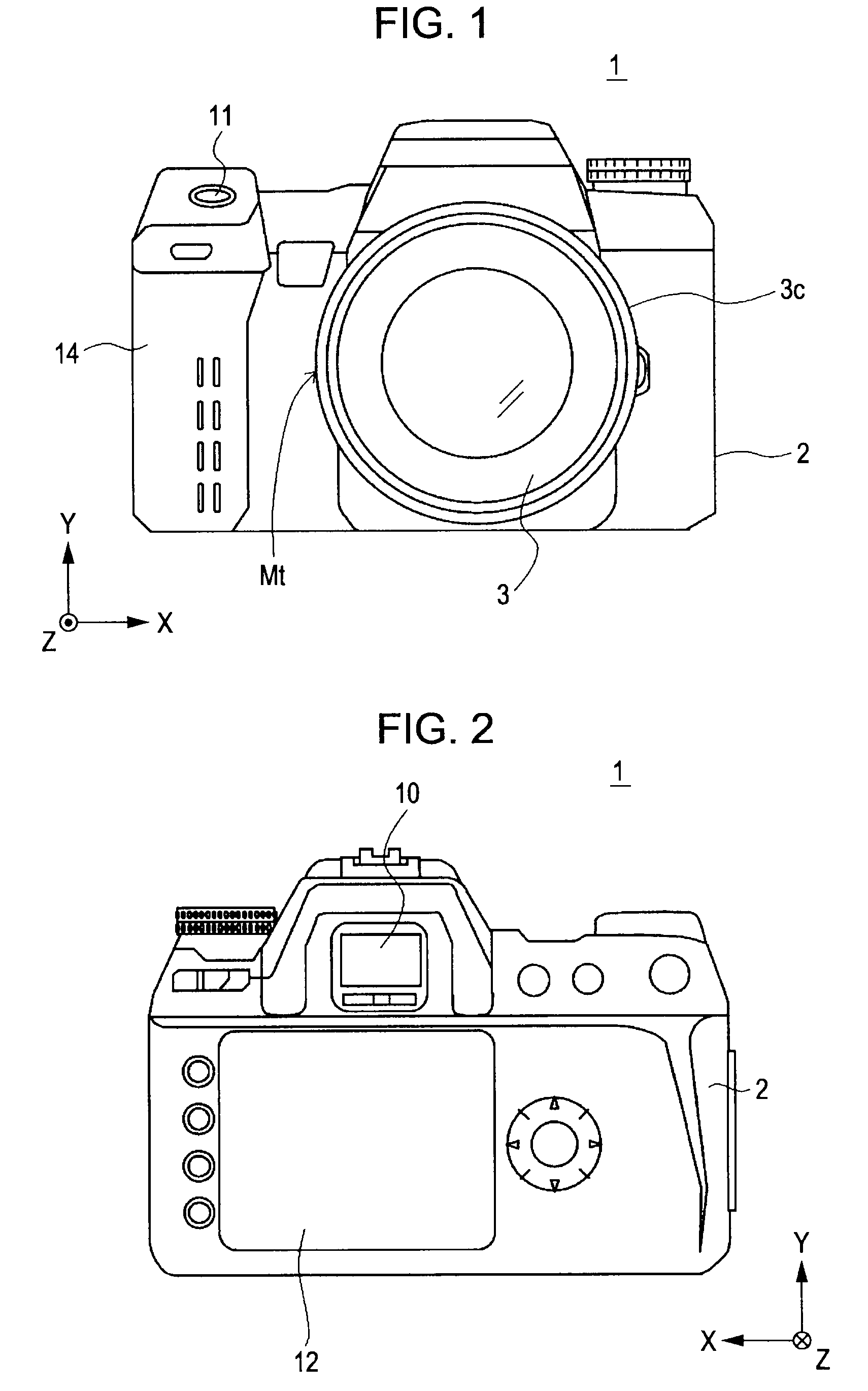
[0031]FIGS. 1 and 2 are external views of the structure of an image pickup apparatus 1 according to the embodiment of the present invention. Here, FIG. 1 is a front external view of the image pickup apparatus 1, and FIG. 2 is a rear external view of the image pickup apparatus 1. The image pickup apparatus 1 is formed as a digital camera of a lens-replacement single-lens reflex type.

[0032]As shown in FIG. 1, the image pickup apparatus 1 includes a camera body 2. A replacement-type shooting lens unit (replacement lens) 3 is removable with respect to the camera body 2.

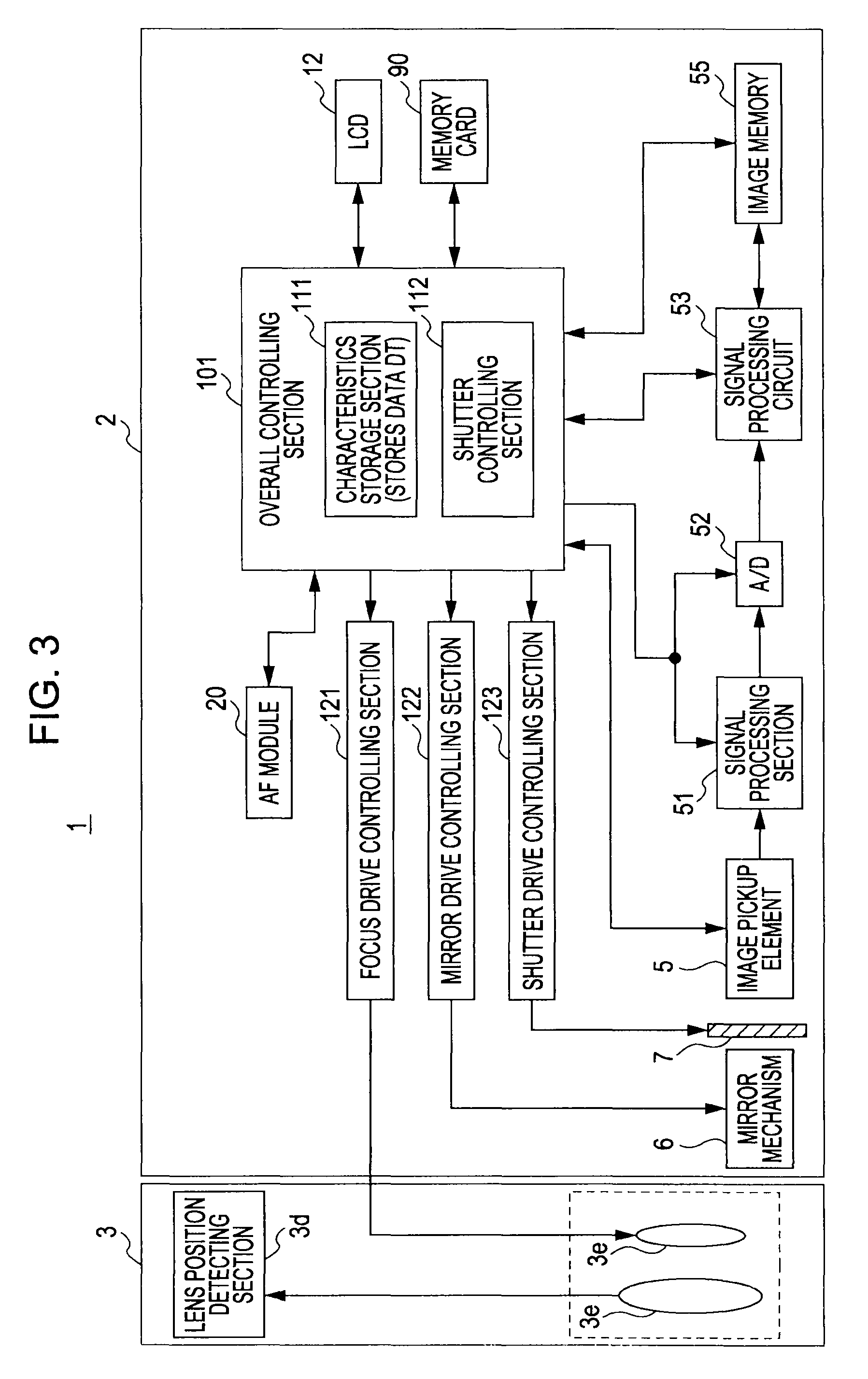
[0033]The shooting lens unit 3 primarily includes, for example, a barrel 3c, a lens group 3e (see FIG. 3), provided in the barrel 3c, and a stop. The lens group 3e (shooting optical system) includes, for example, a focus lens that changes a focus position by moving in an optica...


PUM


Abstract

An image pickup apparatus includes a controlling unit moving an electronic front curtain in a simulated manner from an exposure start position towards an exposure end position by successively performing reset operations on a plurality of pixels in an image pickup element in a predetermined direction; a rear curtain that moves from the exposure start position towards the exposure end position by a biasing force of a biasing unit; and a storage unit storing data indicating a change in movement characteristics of the rear curtain with time. On the basis of the data, the controlling unit changes movement characteristics of the electronic front curtain in accordance with the change in the movement characteristics of the rear curtain with the time.

Description

BACKGROUND OF THE INVENTION[0001]1. Field of the Invention[0002]The present invention relates to an image pickup apparatus, such as a digital camera. More particularly, the present invention relates to a shutter control technology.[0003]2. Description of the Related Art[0004]As a shutter device used in an image pickup apparatus, a shutter device that successively moves a front blade group (front curtain) and a rear blade group (rear curtain) and that performs an exposure operation using a slit formed between both of the blade groups (that is, between the front curtain and the rear curtain) is available. In such a shutter device, the front curtain and the rear curtain are moved in predetermined directions from an exposure start position towards an exposure end position by biasing forces of springs, respectively.[0005]In recent years, an image pickup apparatus in which, among a front curtain and a rear curtain of a shutter device, the front curtain is replaced by one that performs ele...

Claims


Application Information

Patent Timeline
Patent Type & Authority Patents(United States)
IPC IPC(8): H04N5/235G03B7/12H04N3/14G03B7/00H04N5/238H04N101/00
CPCG03B7/093
Inventor TANAKA, YOSHIHARUMURASHIMA, NOBUHARU
Owner SONY CORP
Why Eureka
Try Eureka