Dishwasher with soil removal

a dishwasher and soil technology, applied in the field of dishwashing, can solve the problems of clogging or blocking the filter used to circulate liquid, and achieve the effect of reducing the number of clogging or blocking of the filter

Inactive Publication Date: 2012-07-10
WHIRLPOOL CORP
View PDF24 Cites 50 Cited by
  • Summary
  • Abstract
  • Description
  • Claims
  • Application Information

AI Technical Summary

Problems solved by technology

The filters used to filter the liquid to be circulated often become clogged or blocked with filtered soil that may accumulate over time or soil that does not drain completely from the sump.

Method used


Image

  • Dishwasher with soil removal
  • Dishwasher with soil removal
  • Dishwasher with soil removal

Examples


Embodiment Construction

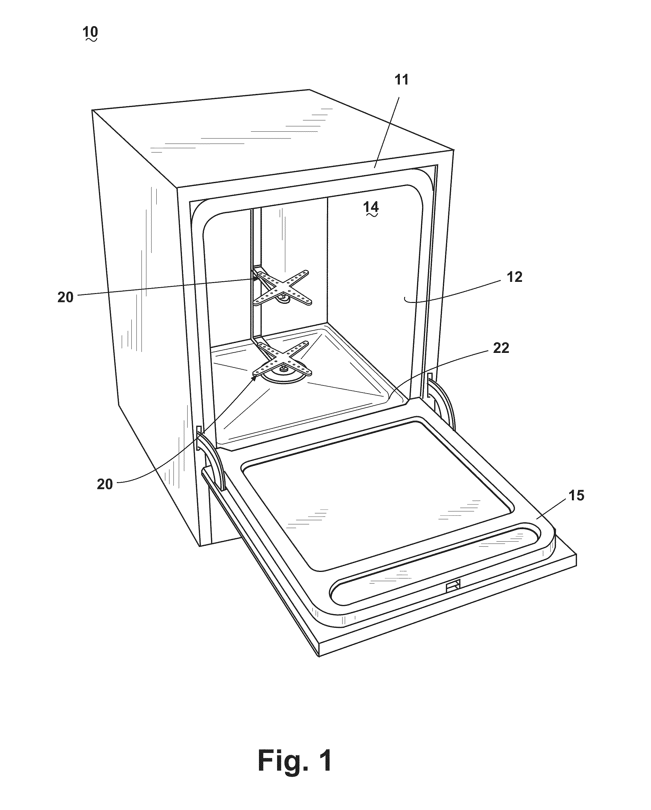
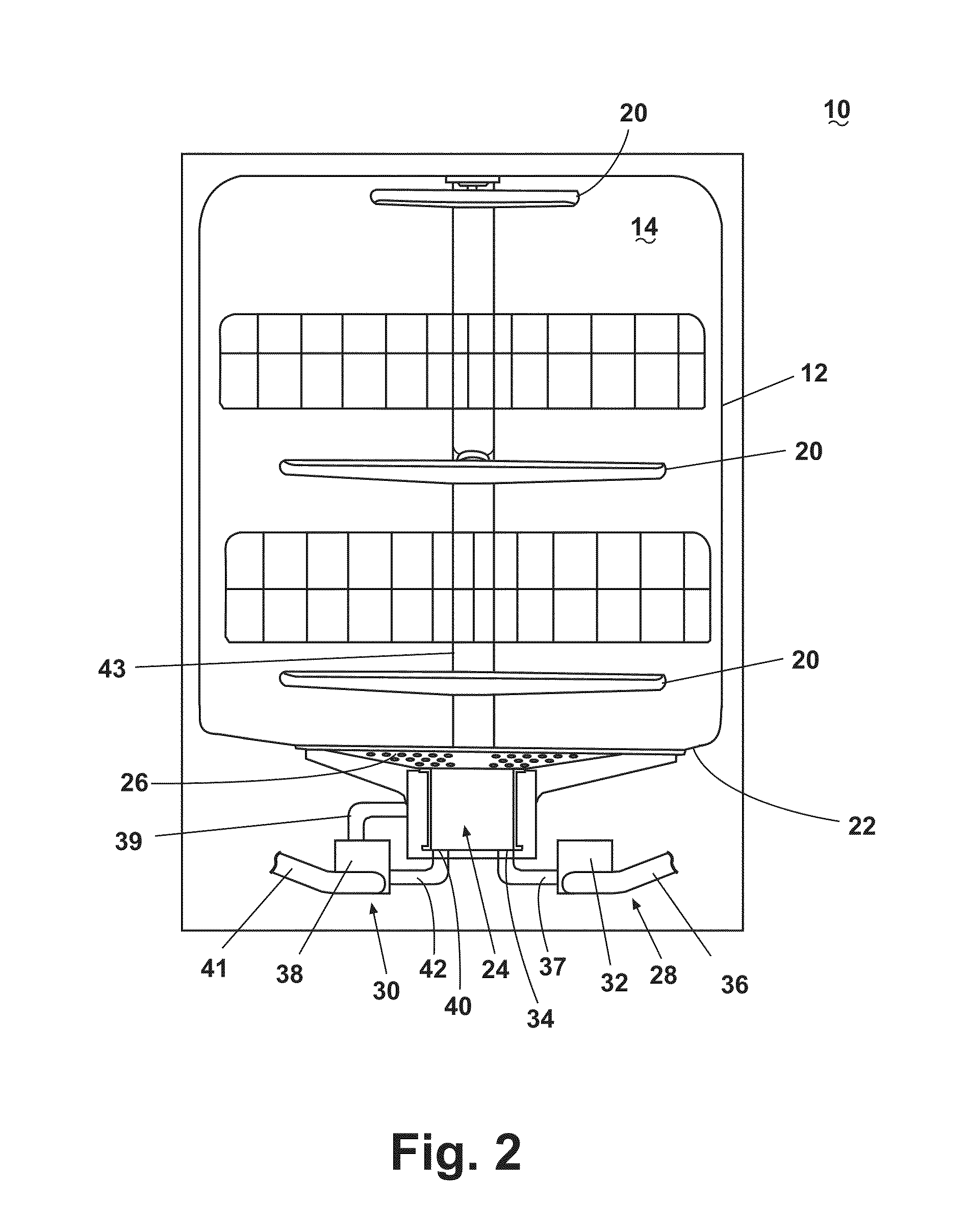
[0015]Referring now to the figures, FIG. 1 illustrates a dishwasher 10 according to one embodiment of the invention. The dishwasher 10 comprises cabinet 11 in which is provided a tub 12 defining a wash chamber 14 in which utensils are received for washing. A door 15 may be provided for selective access to the wash chamber 14. The wash chamber 14 may comprise one or more sprayers 20 from which liquid may be sprayed for washing utensils placed within the wash chamber 14. The sprayers 20, while illustrated as rotating arms, may be fixed and may have a configuration other than an arm. As best seen in FIG. 2, the bottom 22 of the tub 12 may slope towards a sump 24 that may be covered by a grating 26.

[0016]The dishwasher 10 may further comprise a drain circuit 28 and a circulation circuit 30. The drain circuit 28 may be fluidly connected with the sump 24 to drain liquid and soil that collect in the sump 24 through one or more drain inlets 34 located at the bottom of the sump 24. The drain...


PUM


Abstract

The invention relates to a dishwasher comprising a tub in which utensils and the like are received for cleaning by the spraying of liquid, such as a wash liquid, within the tub, with a sequester located within the tub to sequester the particles removed from the utensils by the liquid and that remain in the tub near a drain outlet.

Description

BACKGROUND OF THE INVENTION[0001]In a conventional dishwasher, liquid is sprayed onto the wash load in the wash chamber to remove soil from the utensils placed in the dishwasher. The liquid and soil removed from the utensils accumulates in the sump of the dishwasher where they can be removed from the sump through a drain. To minimize water consumption, many dishwashers further comprise a circulation circuit that reuses water that accumulates in the sump to clean the utensils placed in the dishwasher.[0002]Typically, a filter will be located in or near the sump to filter or partially filter the liquid before it is circulated back to the wash chamber. The filters used to filter the liquid to be circulated often become clogged or blocked with filtered soil that may accumulate over time or soil that does not drain completely from the sump.SUMMARY OF THE INVENTION[0003]In one embodiment, the invention relates to a dishwasher comprising a tub that defines a wash chamber for washing utensi...

Claims


Application Information

Patent Timeline
Patent Type & Authority Patents(United States)
IPC IPC(8): B08B3/04B08B3/00
CPCA47L15/4204
Inventor FOUNTAIN, JORDAN ROBERTKEHL, DENNIS L.TOMEY, JAMES P.WELCH, RODNEY M.
Owner WHIRLPOOL CORP
Why Eureka
Try Eureka