Rail wiring duct

Active Publication Date: 2012-07-10
PANDUIT
View PDF44 Cites 13 Cited by
  • Summary
  • Abstract
  • Description
  • Claims
  • Application Information

AI Technical Summary

Problems solved by technology

While space is generally limited in the enclosure, as well as the surrounding environment, a sufficient amount of space must be provided for dissipating heat generated by the electronic components and for accessing the electronic components, as well as an interior portion of the wiring ducts.

Method used


Image

  • Rail wiring duct
  • Rail wiring duct
  • Rail wiring duct

Examples


first embodiment

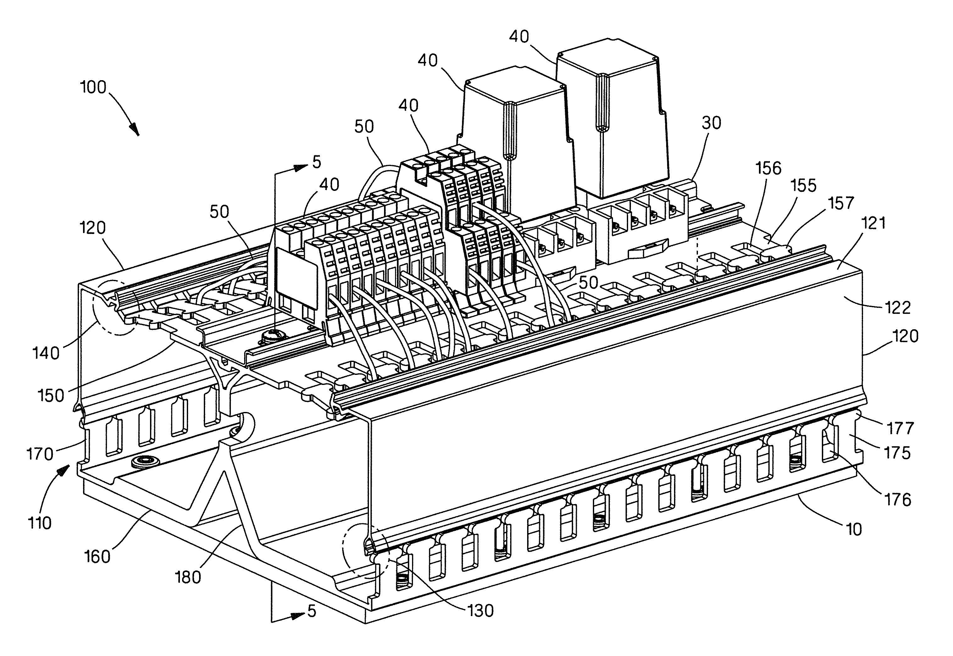
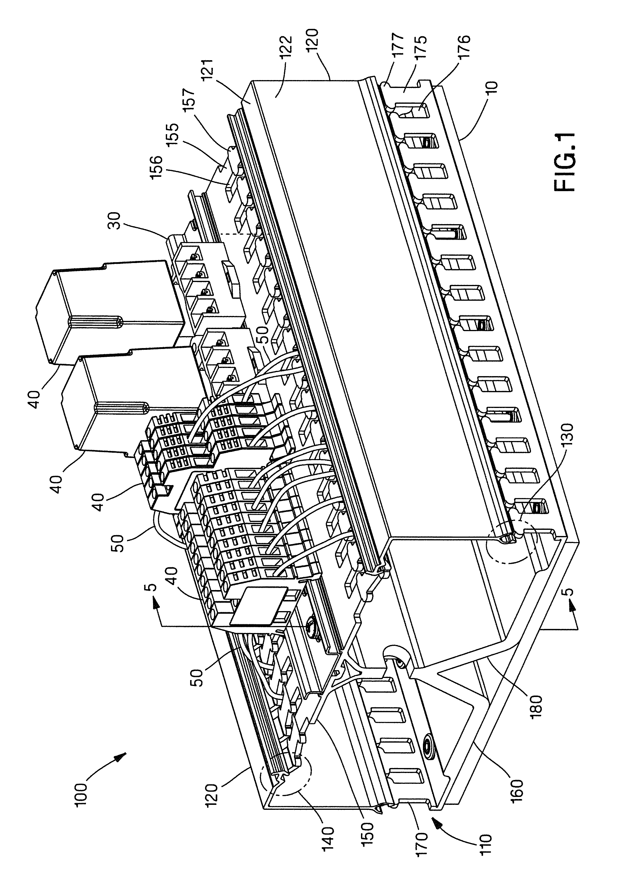
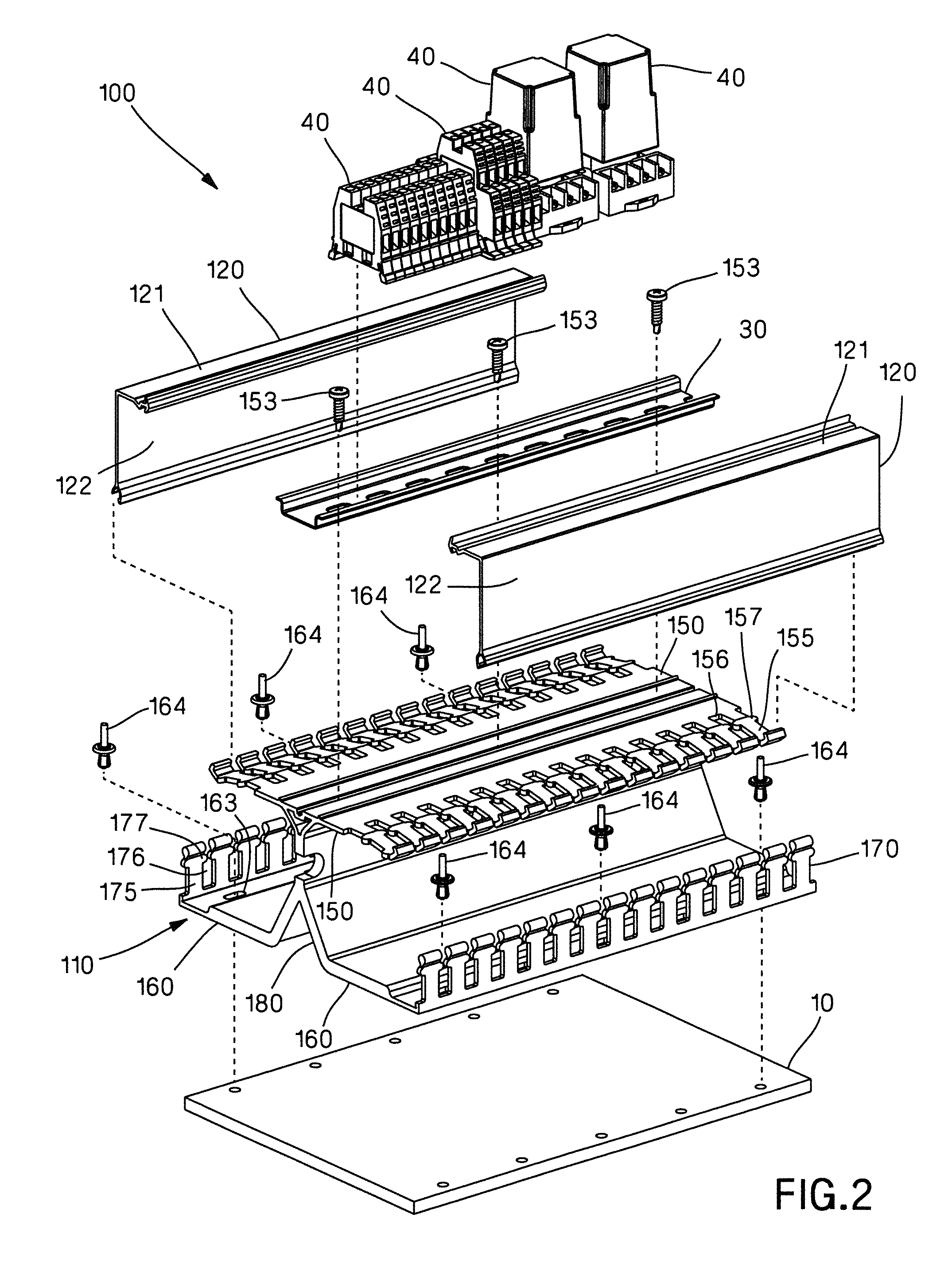
[0034]FIGS. 1-10 illustrate a rail wiring duct 100 according to the present invention. The rail wiring duct 100 includes a base 110 and two covers 120. Each of the covers 120 is attached to the base 110 by a hinge mechanism 130 on one side and a latch mechanism 140 on the other side. The rail wiring duct 100 may be formed from any suitable material, but is preferably formed from a plastic material, such as polyvinylchloride (“PVC”). The rail wiring duct 100 is preferably formed by extrusion followed by one or more secondary operations, such as punching of fingers and holes, as necessary.

[0035]As shown in FIG. 1, the rail wiring duct 100 is secured to a backplane 10 of an industrial enclosure (not shown). A DIN rail 30 is secured to the rail wiring duct 100, and DIN rail mounted components 40, such as cube relays, feed through terminal blocks, PLC interface modules, servo control breakout boards, circuit breaker terminal blocks, and / or fused terminal blocks, are secured to the DIN ra...

second embodiment

[0046]FIGS. 14-18 illustrate a rail wiring duct 200 according to the present invention. The rail wiring duct 200 is similar to the rail wiring duct 100 of FIG. 1, except that the rail wiring duct 200 includes an angled, dual hinge-cover 220 and a removable divider wall 280.

[0047]As best seen in FIG. 16, the cover 220 is oriented at an angle A of about 45 degrees with respect to the bottom wall 260 of the base 210. The angle A may be varied from about 0 degrees to about 90 degrees. Varying the angle A of the cover 220 changes the profile of the rail wiring duct 200, which may be advantageous in installations where space is limited.

[0048]As best seen in FIGS. 16-17, each of the covers 220 includes two hinge mechanisms 230, which allow the cover 220 to rotate from a closed position CP, as shown in FIG. 16, to one of two open positions OP1, OP2, as shown in FIG. 17. Additionally, the cover 220 is removable at one or both of the hinge mechanisms 230.

[0049]As best seen in FIG. 18, the top...

third embodiment

[0050]FIGS. 19-23 illustrate a rail wiring duct 300 according to the present invention. The rail wiring duct 300 is similar to the rail wiring duct 100 of FIGS. 1-13, except that the rail wiring duct 300 includes an elevated, dual-hinge cover 320 and an integrally formed, removable top wall 350 and divider wall 380.

[0051]As best seen in FIG. 21, the top wall 350 of the base 310 is substantially U-shaped and includes top wall fingers 355. The top wall fingers 355 are substantially parallel to the sidewall fingers 375 and extend beyond the DIN rail 30. Consequently, the covers 320 are elevated with respect to the DIN rail 30. Compared to the rail wiring duct 100 of FIGS. 1-10, the sidewalls 322 of the cover 320 have been shortened and the sidewalls 370 of the base 310 have been lengthened, although other configurations are likewise contemplated. Additionally, similar to the sidewall fingers 375, the top wall fingers 355 are vertically oriented, and thus, easier to manufacture using ex...


PUM


Abstract

Certain embodiments of the present invention provide a DIN rail wiring duct. The DIN rail wiring duct has a top, a bottom, and a side. The DIN rail wiring duct includes a base. The base has a top wall, a bottom wall, a sidewall, and a divider wall, which define a channel and a channel opening for accessing the channel. The DIN rail wiring duct also includes a cover for the channel opening. The cover has a top wall and a sidewall substantially perpendicular to the top wall. The top wall of the cover is removably connected to the top wall of the base and the sidewall of the cover is rotatably connected to the sidewall of the base such that the channels are accessible through the channel openings from the top and the side of the DIN rail wiring duct when the cover is rotated from a closed position to an open position.

Description

CROSS-REFERENCE TO RELATED APPLICATIONS[0001]This application claims priority to U.S. Provisional Application No. 61 / 027,965, filed Feb. 12, 2008.BACKGROUND OF THE INVENTION[0002]The present invention relates to an industrial enclosure, and more particularly, to a wiring duct for the industrial enclosure.[0003]Typically, electronic components, such as cube relays, feed through terminal blocks, PLC interface modules, servo control breakout boards, circuit breaker terminal blocks, and / or fused terminal blocks, are mounted to a DIN rail, and in turn, the DIN rail is mounted to an industrial enclosure, such as a control panel, which protects the electronic components from the surrounding environment. Wiring ducts are disposed on either side of the DIN rail for routing cables to and from the electronic components.[0004]While space is generally limited in the enclosure, as well as the surrounding environment, a sufficient amount of space must be provided for dissipating heat generated by ...

Claims


Application Information

Patent Timeline
Patent Type & Authority Patents(United States)
IPC IPC(8): H02G3/06H02G3/04
CPCH02G3/0418H02G3/045H02G3/105
Inventor CAVENEY, JACK E.DORMAN, FRED L.STABRAWA, MICHAEL R.GROFF, JEFF K.
Owner PANDUIT
Why Eureka
Try Eureka