
Electronic apparatus and control method thereof

a technology of electronic equipment and control method, applied in the direction of digital output to print unit, dynamo-electric converter control, instruments, etc., can solve the problems of difficult to maintain the quality of electronic equipment, difficult to inspect the connection of electronic components such as solenoids, clutches, motors, sensors, etc., and achieve the effect of easy and reliable inspection of the connection of electronic components

Inactive Publication Date: 2012-07-24
CANON KK
View PDF25 Cites 0 Cited by
  • Summary
  • Abstract
  • Description
  • Claims
  • Application Information

AI Technical Summary

Benefits of technology

[0007]The present invention enables to easily and reliably inspect connections of electronic components of an electronic apparatus.

Problems solved by technology

However, it is difficult to inspect connections of electronic components (such as solenoids, clutches, motors, and sensors) in complicated electronic apparatuses.
For example, it is becoming hard to detect an open-circuit condition caused by a disconnection of a connector or a short circuit caused by a pinched harness, making it difficult to maintain the quality of electronic apparatuses.
Furthermore, conventional methods cannot detect an imperfect connection of an electronic component such as a photo-interrupt sensor in which results of detection by detecting voltages vary depending on the conditions of objects to be detected by the sensor.
Therefore, it was difficult to inspect connections of all components of an apparatus.

Method used


Image

  • Electronic apparatus and control method thereof
  • Electronic apparatus and control method thereof
  • Electronic apparatus and control method thereof

Examples


first embodiment

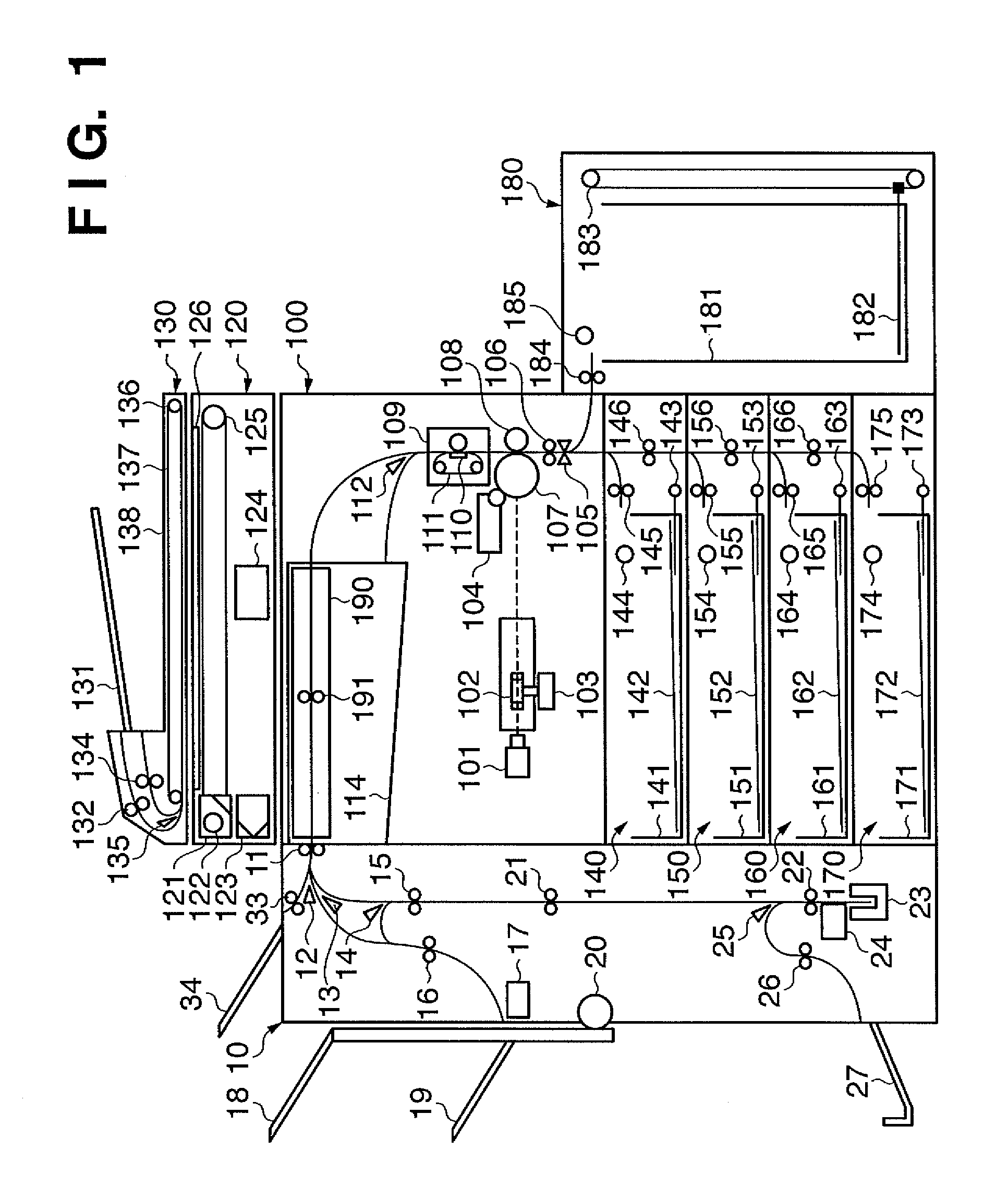
[0023]An image forming apparatus, which is a first embodiment of an electronic apparatus according to the present invention, will be described below. FIG. 1 shows a configuration of a digital multifunction apparatus, which is an exemplary image forming apparatus. While an image forming apparatus will be described in the embodiment, the present invention is not limited to this but is applicable to any electronic apparatus.

[0024]Originals set on an original tray 131 in an original feeder 130 are fed by feeding rollers 132 one by one and are conveyed to an original reading position by an original conveying belt 137 driven by a motor 136. At the original reading position, an original reader 120 reads the original. After the original is read, the original conveying belt 137 rotates in the direction opposite to the initial rotation when the originals were set, thereby conveying the original in the opposite direction. In this conveyance, a flapper 135 changes the conveying path to discharg...

second embodiment

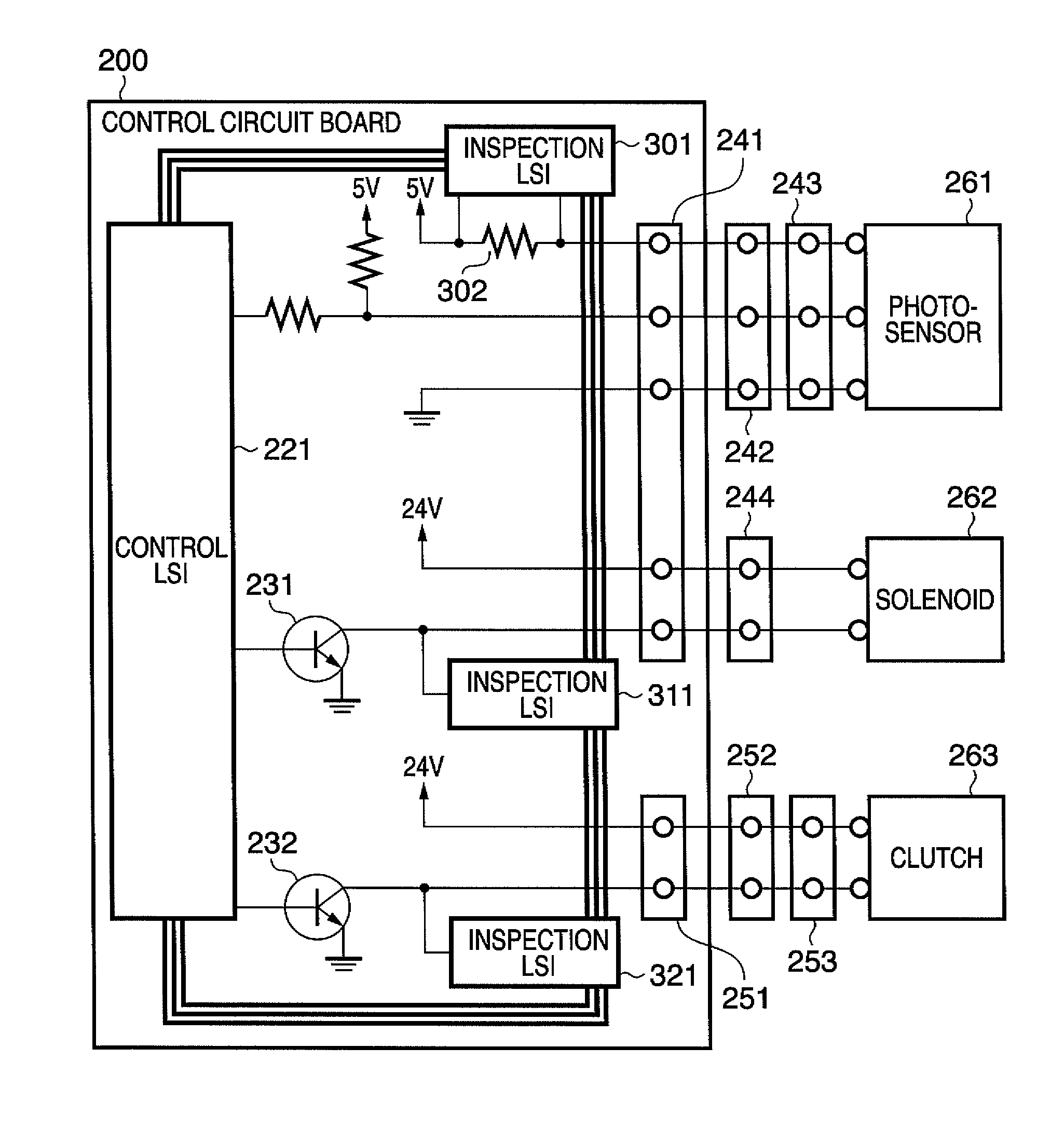
[0051]While all inspection LSIs and the control LSI are synchronized using the clock in the first embodiment, the present invention is not limited to this. For example, all inspection LSIs may be connected in line and a control LSI may be connected at the end.

[0052]When an electronic component is in connection, two pulses High-High are output in the inspection LSI; when an electronic component is not connected, pulses High-Low are output. The two pulses are delayed for a predetermined amount of time and superimposed. By counting the first of the two pulses, the number of the electronic circuits can be known. By identifying an inspection LSI in which the second one of the two pulses is low, an electronic component that is not properly connected can be identified without needing to synchronize the LSIs with each other using a clock.

[0053]This configuration has the advantageous effect that the need for providing the clock and Start signal lines is eliminated and the entire circuitry ca...


PUM


Abstract

The present invention enables connections of electronic components of an electronic apparatus to be inspected easily and reliably. To accomplish this, an electronic apparatus including a plurality of electronic components, includes a control circuit which controls input and output of an electric signal to and from the plurality of electronic components and a plurality of inspection circuits which inspect connections of the plurality of electronic components. The plurality of inspection circuits are connected in series, the control circuit is connected to an end of the series, inspection signals output from the plurality of inspection circuits are superimposed on one another in sequence into an signal and the signal is input into the control circuit, and determination is made at the control circuit as to whether each of the plurality of electronic components is connected properly or not.

Description

BACKGROUND OF THE INVENTION[0001]1. Field of the Invention[0002]The present invention relates to a technique for inspecting whether electronic components of an electronic apparatus are connected properly or not.[0003]2. Description of the Related Art[0004]Connections of electronic components of electronic apparatuses having simple configurations have been inspected by detecting a voltage applied to each electronic component (Japanese Patent Laid-Open No. 2002-286782).[0005]However, it is difficult to inspect connections of electronic components (such as solenoids, clutches, motors, and sensors) in complicated electronic apparatuses. For example, it is becoming hard to detect an open-circuit condition caused by a disconnection of a connector or a short circuit caused by a pinched harness, making it difficult to maintain the quality of electronic apparatuses.[0006]Furthermore, conventional methods cannot detect an imperfect connection of an electronic component such as a photo-interru...

Claims


Application Information

Patent Timeline
Patent Type & Authority Patents(United States)
IPC IPC(8): G01R31/04
CPCG01R31/046G03G15/55G01R31/70
Inventor ISEKI, YUKIMASA
Owner CANON KK
Learn More