Al technical title is built by PatSnap Al team. It summarizes the technical point description of the patent document.
a surgical device and jaw technology, applied in the field of surgical devices, can solve the problems of insufficient hemostaticity of the size of the incision limits the degree to which the jaws may be maneuvered, and the difficulty of maneuvering the jaws of the opposing jaws within the patien
Active Publication Date: 2012-08-14
TYCO HEALTHCARE GRP LP
View PDF9 Cites 1917 Cited by
Summary
Abstract
Description
Claims
Application Information
AI Technical Summary
This helps you quickly interpret patents by identifying the three key elements:
Problems solved by technology
Method used
Benefits of technology
Problems solved by technology
One problem with the foregoing surgical devices, and in particular with the foregoing linear clamping, cutting and stapling devices such as that illustrated in FIG. 1, is that the opposing jaws may be difficult to maneuver within a patient.
However, it is also generally desirable to make an incision in a patient that is as small as possible, and the small size of an incision limits the degree to which the opposing jaws may be maneuvered.
Another problem with the foregoing surgical devices, and in particular with the foregoing linear clamping, cutting and stapling devices such as that illustrated in FIG. 1, is that the opposing jaws may not be sufficiently hemostatic.
Specifically, the opposing jaws of the foregoing surgical devices are not clamped together with sufficient force, thereby reducing the effectiveness of the surgical device.
Method used
Image
Click on the blue label to locate the original text in one second.
Reading with bidirectional positioning of images and text.
Examples
Embodiment Construction
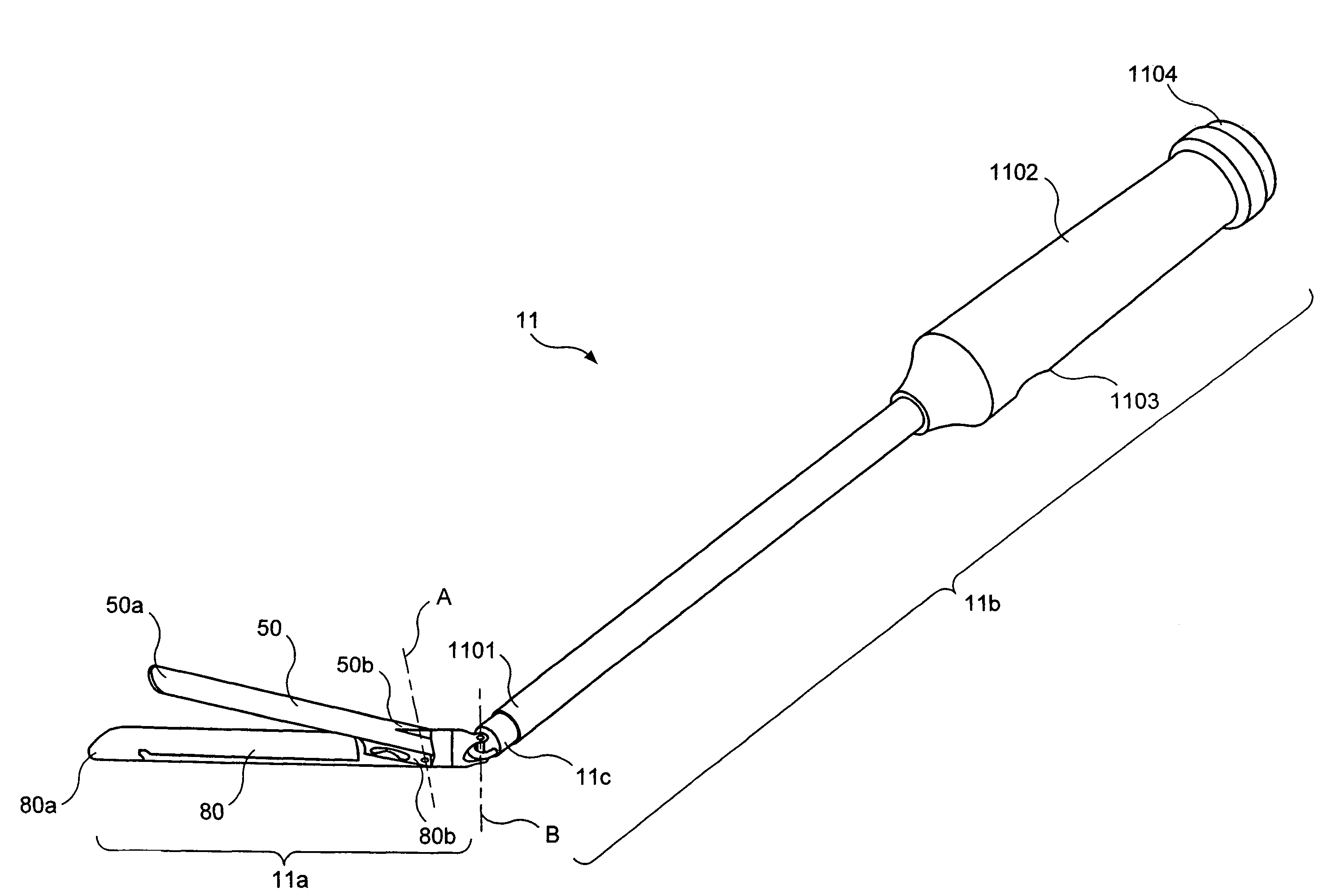
[0048]FIG. 2(b) is a schematic diagram that illustrates some of the components of a surgical device 11, according to an example embodiment of the present invention. The surgical device 11 is configured so as to be particularly well-suited for insertion into the body of a patient, e.g., via a cannula (not shown). In the embodiment shown, the surgical device 11 is a clamping, cutting and stapling device. The surgical device 11 includes a jaw portion 11a that is pivotably coupled to a shaft portion 11b by a hinge portion 11c. The jaw portion 11a includes a first jaw 50 having a distal end 50a and a proximal end 50b, and a second jaw 80 having a distal end 80a and a proximal end 80b. The first jaw 50 and the second jaw 80 are pivotably coupled relative to each other at or near their respective proximal ends 50b, 80b. In the example embodiment shown, the first jaw 50 and the second jaw 80 pivot relative to each other about pivot axis A, which is oriented perpendicular to the page.
[0049]A...
PUM
Property
Measurement
Unit
angle
aaaaa
aaaaa
rotation
aaaaa
aaaaa
flexible
aaaaa
aaaaa
Abstract
A surgical device is provided that includes a jaw portion with a first jaw and a second jaw moveable relative to the first jaw. The surgical device also includes a shaft portion coupled to a proximal end of the jaw portion. A driver is configured to cause relative movement of the jaw portion and the shaft portion. The driver may be configured to cause the jaw portion to pivot relative to the shaft portion about a pivot axis that is perpendicular to first and second longitudinal axes defined by the jaw portion and the shaft portion, respectively. The driver may also be configured to cause at least a portion of the jaw portion to rotate relative to the shaft portion about the first longitudinal axis. Advantageously, the surgical device includes a surgical member, e.g., a cutting element and / or a stapling element, disposed within the first jaw.
Description
CROSS-REFERENCE TO RELATED APPLICATIONS[0001]The present application expressly incorporates herein by reference each of the following in its entirety: U.S. Patent Application Ser. No. 60 / 388,644, filed on Jun. 14, 2002; U.S. patent application Ser. No. 10 / 460,291, filed on Jun. 11, 2003; U.S. patent application Ser. No. 09 / 999,546, filed on Nov. 30, 2001; U.S. patent application Ser. No. 09 / 887,789, filed on Jun. 22, 2001; U.S. patent application Ser. No. 09 / 836,781, filed on Apr. 17, 2001; U.S. patent application Ser. No. 09 / 723,715, filed on Nov. 28, 2000; U.S. patent application Ser. No. 09 / 324,451, filed on Jun. 2, 1999, and issued as U.S. Pat. No. 6,315,184 on Nov. 13, 2001; U.S. patent application Ser. No. 09 / 324,452, filed on Jun. 2, 1999, and issued as U.S. Pat. No. 6,443,973 on Sep. 3, 2002; U.S. patent application Ser. No. 09 / 351,534, filed on Jul. 12, 1999 and issued as U.S. Pat. No. 6,264,087 on Jul. 24, 2001; U.S. patent application Ser. No. 09 / 510,923, filed on Feb. 22...
Claims
Application Information
Patent Timeline
Application Date:The date an application was filed.
Publication Date:The date a patent or application was officially published.
First Publication Date:The earliest publication date of a patent with the same application number.
Issue Date:Publication date of the patent grant document.
PCT Entry Date:The Entry date of PCT National Phase.
Estimated Expiry Date:The statutory expiry date of a patent right according to the Patent Law, and it is the longest term of protection that the patent right can achieve without the termination of the patent right due to other reasons(Term extension factor has been taken into account ).
Invalid Date:Actual expiry date is based on effective date or publication date of legal transaction data of invalid patent.