Bottom blade type trefoil flight vehicle

a flight vehicle and blade type technology, applied in vertical landing/take-off aircraft, aircraft navigation control, transportation and packaging, etc., can solve the problems of unstable bottom blade type flight vehicle and power efficiency degradation, and achieve the effect of unfavorable wind flow

Inactive Publication Date: 2012-08-28
SUNTECH ENTERPRISES
View PDF6 Cites 7 Cited by
  • Summary
  • Abstract
  • Description
  • Claims
  • Application Information

AI Technical Summary

Benefits of technology

[0013]Adjacent adjustment blades are arranged at an angle of 120°, other than 90°, so that the distance between the adjacent adjustment blades is widened. The hinge is installed at a lower portion of the fixing plate such that the adjustment blade can be moved only in the left direction about the vertical plane to protect the adjustment blade. In addition, the uneven flow of wind caused by the adjustment blades, which are arranged closely to each other, can be prevented.

Problems solved by technology

The forward and backward adjustment blades and the left and right rotation adjustment blades are moved to the left and right about the vertical plane, respectively, so the distance between adjacent adjustment blades becomes narrowed sometimes. Thus, the flow of wind around the adjacent adjustment blades may become uneven because the wind generated from the adjacent adjustment blades is directed against each other, so that the bottom blade type flight vehicle is unstable and the power efficiency is degraded.

Method used


Image

  • Bottom blade type trefoil flight vehicle
  • Bottom blade type trefoil flight vehicle
  • Bottom blade type trefoil flight vehicle

Examples


Embodiment Construction

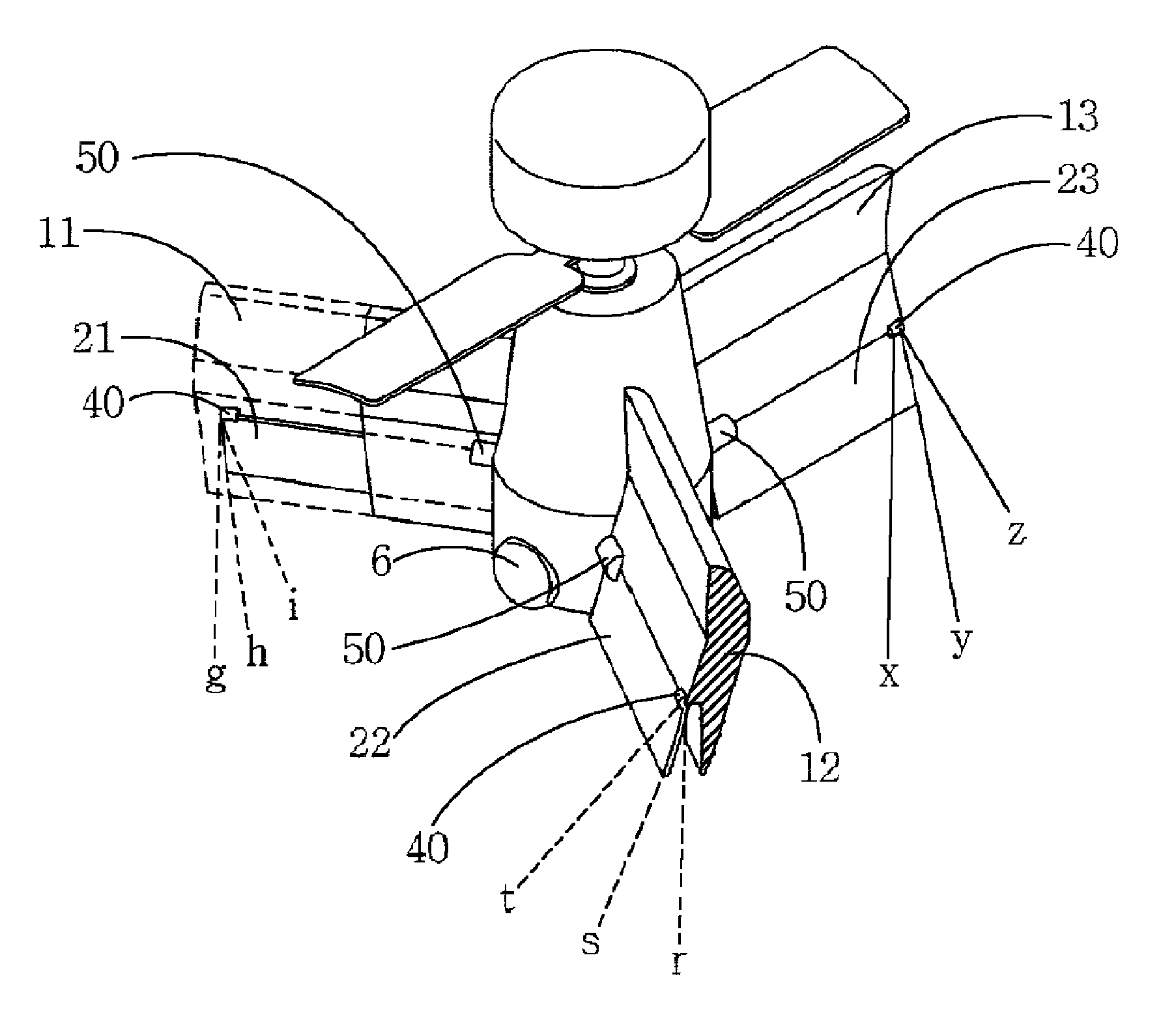
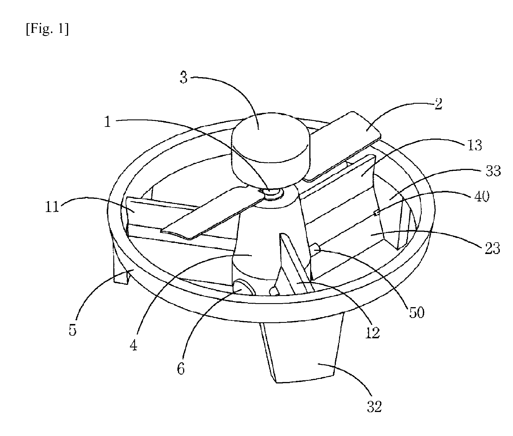
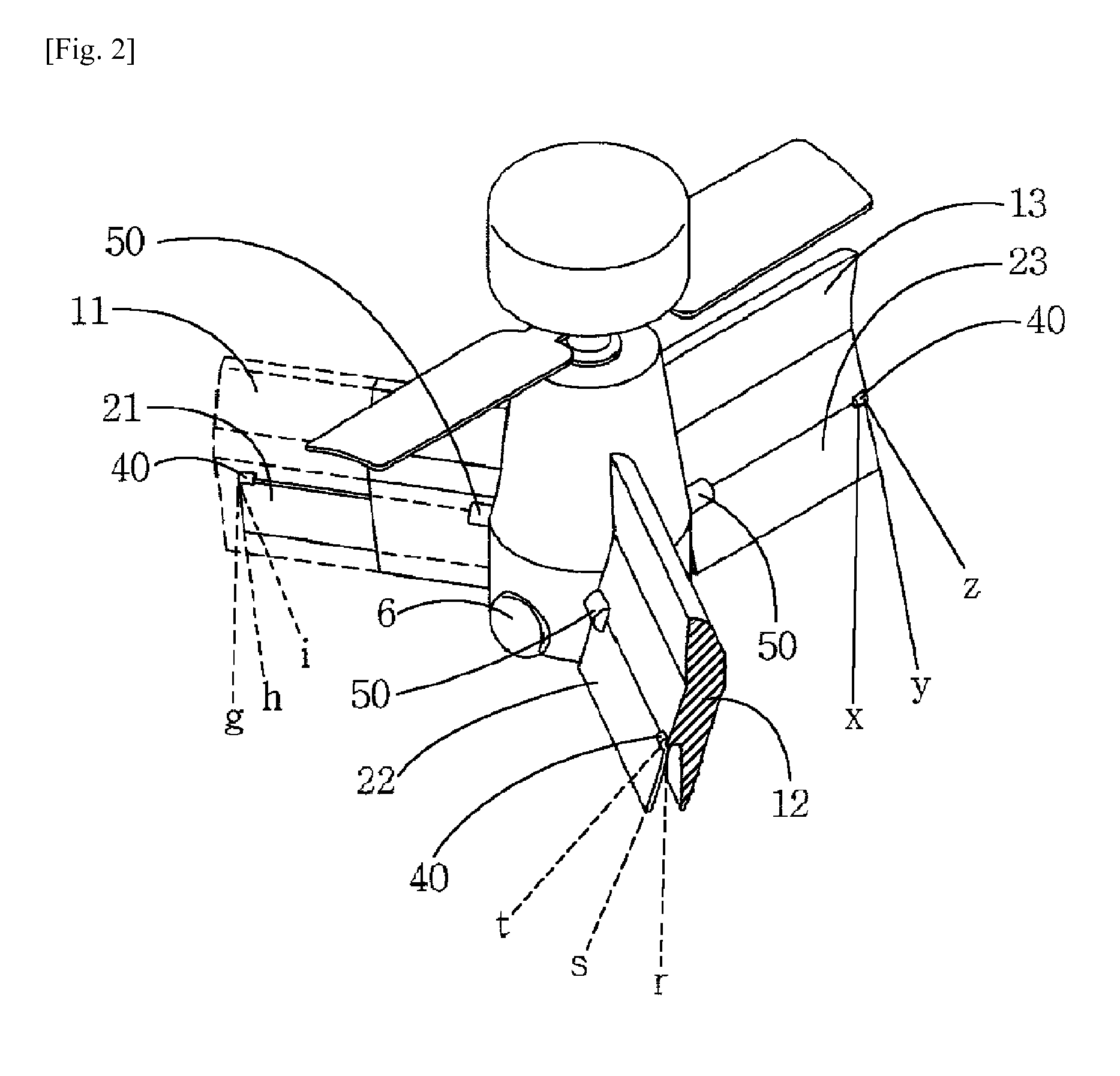
[0021]Hereinafter, a bottom blade type trefoil flight vehicle according to the exemplary embodiment of the present invention will be described with reference to accompanying drawings.

[0022]According to the present invention, a fixed pitch propeller 2 is horizontally mounted about a central shaft 1, a power unit 3 is provided at an upper portion of the central shaft 1, and a control unit 4 is provided at a lower portion of the central shaft 1. First to third fixing plates 11 to 13 are arranged at an angle of 120° in such a manner that one ends of the first to third fixing plates 11 to 13 are longitudinally fixed to the control unit 4 and the other ends of the first to third fixing plates 11 to 13 are longitudinally fixed to a circular frame 5 and leg plats 31, 32 and 33. First to third adjustment blades 21 to 23, which are adjusted by an adjustment device 50 under the control of the control device of the control unit 4, are installed at lower portions of front surfaces of the first t...


PUM


Abstract

Conventional bottom blade type trefoil flight vehicles have composite structures wherein a plurality of pairs of fixing plates, forward / backward adjustment blades, and left and right rotation adjustment blades are separately mounted and adjusted, and thus have difficulties in scouting and surveillance in an indoor area due to the heavy weights and the large volumes of the flight vehicles. Another conventional flight vehicle has drawbacks in that flight in the left and right directions is difficult, and an adjustment blade and a fixing plate are arranged adjacent to each other to cause mutual influences of wind and non-uniformity in the flow of wind. The present invention provides a flight vehicle characterized in that three pairs of fixing plates with fixed pitch propellers and adjustment blades are installed at an angle of 120 degrees. The present invention allows anti-torque, hovering, forward / backward advancing, left and right rotation, and flight in the left and right direction of flight vehicles, and scouting and surveillance in a narrow space. The flight vehicle of the present invention is simple in structure and control, lightweight, and small in size, thereby improving power efficiency.

Description

TECHNICAL FIELD[0001]The present invention relates to a bottom blade type flight vehicle, which is a kind of unmanned rotational blade type flight vehicles.BACKGROUND ART[0002]In general, a bottom blade type flight vehicle includes a propeller and adjustment blades. The bottom blade type flight vehicle rotates the propeller using power and adjusts the adjustment blades for ascending, descending, forward and backward advancing, hovering, left and right rotation, and leftward and rightward advancing.[0003]According to the related art, the bottom blade type flight vehicle includes a plurality of pairs of fixing plates as well as a plurality of pairs of forward and backward adjustment blades and a plurality of pairs of left and right rotation adjustment blades installed to lower portions of the fixing plates while being separated from each other at an angle of 90° to restrict the shake in the front and rear directions of the bottom blade type flight vehicle and the fluctuation in the le...

Claims


Application Information

Patent Timeline
Patent Type & Authority Patents(United States)
IPC IPC(8): B64C27/06
CPCB64C39/028B64C2201/027B64C2201/127B64C2201/088B64C2201/108B64C2201/042B64U70/80B64U10/13B64U30/20B64U50/19B64U2101/31B64C27/54B64C27/32B64U2101/30
Inventor CHOI, KEY NAM
Owner SUNTECH ENTERPRISES
Why Eureka
Try Eureka