Method and system for providing a magnetic head using a composite magnetic material in the recording transducer

Inactive Publication Date: 2012-09-04
WESTERN DIGITAL TECH INC
View PDF17 Cites 157 Cited by
  • Summary
  • Abstract
  • Description
  • Claims
  • Application Information

AI Technical Summary

Benefits of technology

[0006]FIG. 1 is a side view of a co

Problems solved by technology

In such applications, various issues arise.
In addition, heating of the components of the conventional write transducer 10 may result in increased thermo-mechanical stress in the head.
T

Method used


Image

  • Method and system for providing a magnetic head using a composite magnetic material in the recording transducer
  • Method and system for providing a magnetic head using a composite magnetic material in the recording transducer
  • Method and system for providing a magnetic head using a composite magnetic material in the recording transducer

Examples


Embodiment Construction

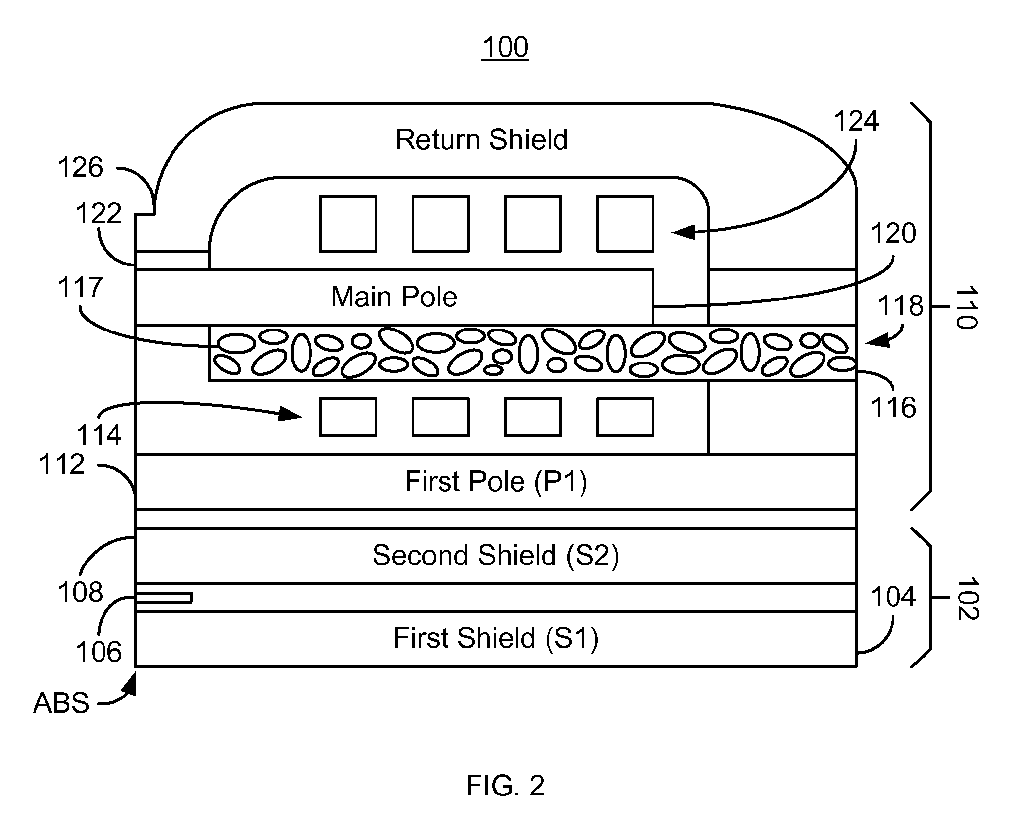
[0014]FIG. 2 is a side view of an exemplary embodiment of a magnetic recording head 100. In one embodiment, the magnetic recording head 100 is a PMR head. However, in another embodiment, the magnetic recording head 100 may be a longitudinal magnetic recording head. In addition, although depicted as including both a read transducer 102 and a write transducer 110, the head 100 may include only a write transducer 110. Alternatively, the head 100 may include multiple read and / or write transducers (not shown). For clarity, FIG. 2 is not drawn to scale.

[0015]The magnetic recording head 100 includes a read transducer 102 and a write transducer 110. The read transducer 102 includes shields 104 and 108 and read sensor 106. The write transducer 110 includes a first pole (P1) 112, a first coil 114, auxiliary pole 116, a main pole 120, write gap 122, a second coil 124, and shield 126. Although the write transducer 110 is depicted with two coils 114 and 124, a single coil may also be used. In ad...


PUM

PropertyMeasurementUnit
Grain sizeaaaaaaaaaa

Abstract

A method and system for providing a magnetic transducer for recording to media is described. The method and system include providing a first pole, a main pole, at least one coil and at least one auxiliary pole. The main pole is for providing a magnetic field for recording to the media. The coil(s) are for energizing the main pole. The auxiliary pole is magnetically coupled with the main pole. The shield(s) are for magnetically isolating a portion of the magnetic transducer. At least one of the first pole, the auxiliary pole, and the at least one shield includes a composite magnetic material including a plurality of ferromagnetic grains in an insulating matrix.

Description

BACKGROUND[0001]FIG. 1 depicts a side view of a conventional magnetic recording head 1 used in recording to and reading from a media (not shown). The conventional magnetic recording head 1 may be a perpendicular magnetic recording (PMR) head or a longitudinal magnetic recording head. The conventional head 1 includes a conventional read transducer 2 and a conventional write transducer 10. The conventional read transducer 2 includes shields 4 and 8 and read sensor 6. The conventional write transducer 10 includes a conventional first pole (P1) 12, a first coil 14, conventional auxiliary pole 16, a conventional main pole 18, conventional write gap 20, a conventional second coil 22, and shield 24. The conventional poles 12, 16, and 18 are typically formed of high saturation magnetization, soft magnetic alloys, such as NiFe, CoNiFe, CoFe, and CoFeN. Such high saturation magnetization, soft magnetic alloys are used in order to ensure that sufficient magnetic field is developed to write to ...

Claims


Application Information

Patent Timeline
IPC IPC(8): G11B5/133
CPCG11B5/3136G11B5/133Y10T29/49032G11B5/3143
Inventor BAI, ZHIGANGSONG, SUPINGGIBBONS, MATTHEW R.MAO, SINING
Owner WESTERN DIGITAL TECH INC
Why Eureka
Try Eureka