Enhanced thermal management of 3-D stacked die packaging

a technology of stacked die packaging and thermal management, which is applied in the direction of cooling/ventilation/heating modification, semiconductor/solid-state device details, semiconductor devices, etc., can solve the problems of degrading the performance of the electronic package with the die stack, difficulty in adequately increasing the bandwidth to memory, and the upper die providing thermal resistan

Active Publication Date: 2012-10-30
INT BUSINESS MASCH CORP
View PDF16 Cites 48 Cited by
  • Summary
  • Abstract
  • Description
  • Claims
  • Application Information

AI Technical Summary

Problems solved by technology

This is especially true with “multicore” chips where it is sometimes difficult to increase the bandwidth to memory adequately.
Despite its benefits, however, a problem with a vertically configured die stack exists in that the upper die provides thermal resistance along the primary heat flow path from the die stack and into the cooling lid (e.g., the lid 120 of FIG. 1).
As a result, performance of the electronic package with a die stack may be degraded.

Method used


Image

  • Enhanced thermal management of 3-D stacked die packaging
  • Enhanced thermal management of 3-D stacked die packaging
  • Enhanced thermal management of 3-D stacked die packaging

Examples


Embodiment Construction

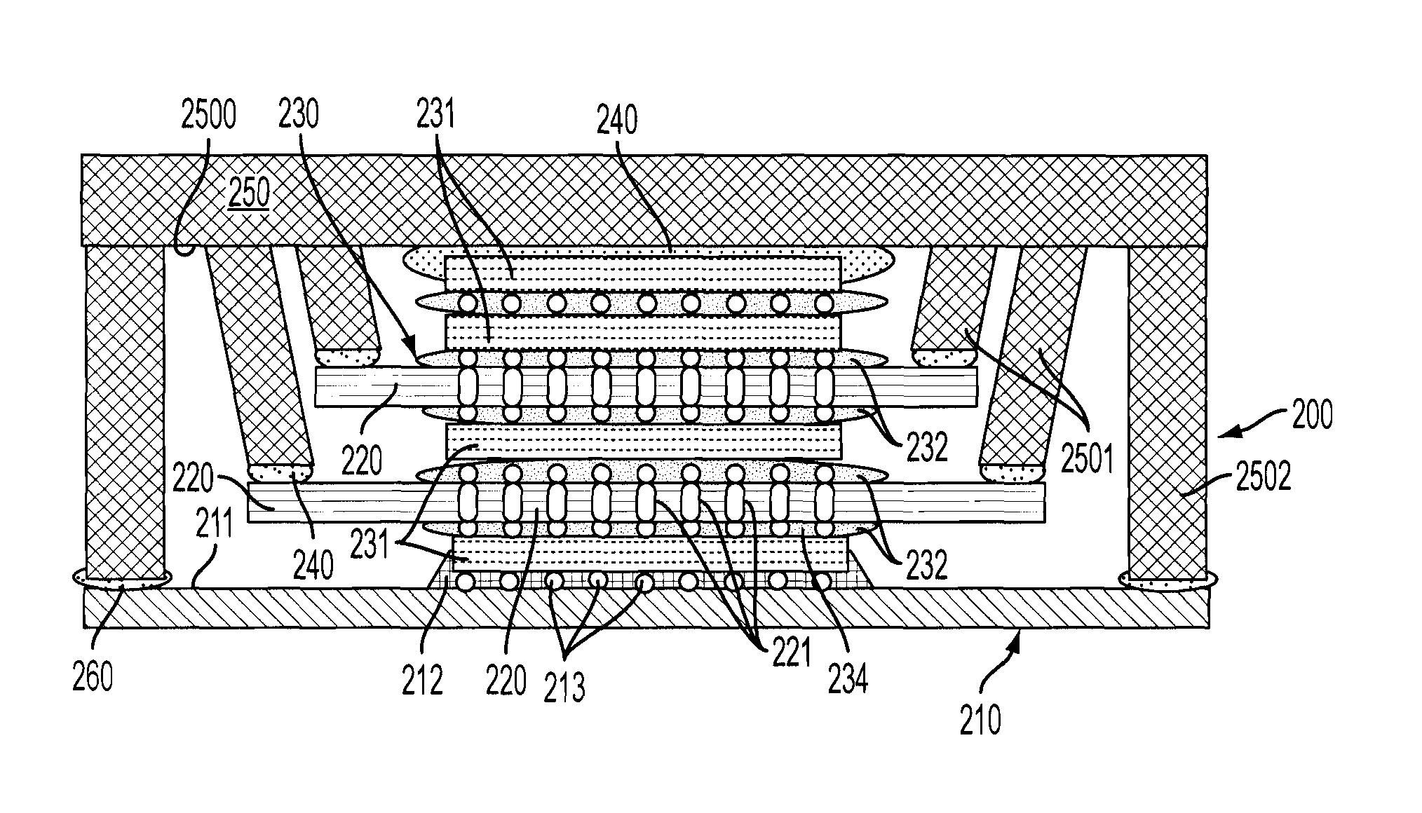
[0020]In accordance with aspects of the invention, an architecture independent cooling solution for die stacks is provided by the addition of a thermal plate to the bottom of the die stack or into a middle of the die stack. Further enhancement in an interconnection between the chips of the die stack and the thermal plate is achieved through thermally conductive adhesive. A lid or heat spreader includes a fin that contacts the thermal plate to provide an additional cooling path for the die stack. The fin may be slanted or coupled to a large area of the lid, such as those areas that would normally be relatively cool regions of the lid. As such, an amount or degree of the die stack cooling is only limited by an overall package size. In addition, de-coupling capacitors and other passive components can be integrated with the thermal plate and cooled as well. Thermal Interface Material (TIM), which is relatively mechanically strong, may be disposed between, for example, the thermal plate ...


PUM


Abstract

A die stack package is provided and includes a substrate, a stack of computing components, at least one thermal plate, which is thermally communicative with the stack and a lid supported on the substrate to surround the stack and the at least one thermal plate to thereby define a first heat transfer path extending from one of the computing components to the lid via the at least one thermal plate and a fin coupled to a surface of the lid and the at least one thermal plate, and a second heat transfer path extending from the one of the computing components to the lid surface without passing through the at least one thermal plate.

Description

BACKGROUND[0001]Aspects of the present invention are directed to enhanced thermal management of 3-D stacked die packaging.DESCRIPTION OF THE BACKGROUND[0002]Generally, an electronic package is a hardware component in which active devices, such as logic or memory devices, and passive devices, such as resistors and capacitors, are enclosed. The electronic package performs functions of an electronic system, such as those used inside a mobile phone, a personal computer, a digital music player, etc. Common electronic packages are classified as either flip-chip or wire-bond packages.[0003]In a typical flip-chip electronic package, as shown in FIG. 1, a single die 10 is joined to a ceramic or organic material substrate 100 through controlled collapse chip connection (C4) bumps 130, which may be encapsulated in an underfill material 160. A lid 120 provides thermal cooling and mechanical protection for the die 10. A thermal interface material (TIM) 150, which can be an elastomer, adhesive, g...

Claims


Application Information

Patent Timeline
Patent Type & Authority Patents(United States)
IPC IPC(8): H01L23/36H01L21/58
CPCH01L23/055H01L23/147H01L23/3677H01L23/433H01L23/49827H01L25/0657H01L23/14H01L2224/16235H01L23/42H01L24/16H01L2224/16146H01L2224/16227H01L2224/3003H01L2224/32245H01L2224/3303H01L2224/73204H01L2224/73253H01L2225/06513H01L2225/06517H01L2225/06572H01L2225/06589H01L2924/01004H01L2924/10253H01L2924/10271H01L2924/16195H01L2924/163H01L2924/167H01L2224/16145H01L2224/32145H01L2224/32225H01L2224/16225H01L2924/00H01L2924/00014H01L2224/0401H01L23/3675
Inventor BARTLEY, GERALD K.MOTSCHMAN, DAVID R.SIKKA, KAMAL K.WAKIL, JAMIL A.WEI, XIAOJINZHENG, JIANTAO
Owner INT BUSINESS MASCH CORP
Why Eureka
Try Eureka