Arrangement for current limiting

a current limit and arrangement technology, applied in the direction of superconductor devices, connection contact material, cables, etc., can solve the problems of significant increase in the resistance of phase conductors, increase in the electrical impedance of components, and noticeably and quickly limited short-circuit current flowing through the arrangemen

Inactive Publication Date: 2012-11-06
NEXANS
View PDF5 Cites 7 Cited by
  • Summary
  • Abstract
  • Description
  • Claims
  • Application Information

AI Technical Summary

Benefits of technology

[0013]When, in one preferred embodiment of the arrangement, only three components of the superconducting cable are used, then only a small number of contacts are required for connection of the phase conductors. This reduces the contact-dependent losses, particularly when first-generation superconducting conductors, for example BSCCO conductors, are used for connecting the respective phase conductors. The cyclic through-connection of the three different phase conductors in the three different components of the arrangement is particularly advantageous because this results in the entire arrangement having a particularly uniform impedance. An arrangement with three components also allows the arrangement to be made very compact, with the cryostat having a relatively small surface area, and correspondingly low thermal losses. During normal operation, the mutual compensation means that no electromagnetic fields occur outside the concentric arrangement of the phase conductors in each component. No eddy currents can therefore be induced in the cryostat, which would likewise lead to losses.

Problems solved by technology

In this state, the ReBCO material is electrically poorly conductive, thus directly resulting in a major increase in the resistance of the phase conductors, that is to say an increase in the electrical impedance of the components.
The short-circuit current flowing via the arrangement is therefore noticeably and quickly limited.
No eddy currents can therefore be induced in the cryostat, which would likewise lead to losses.

Method used


Image

  • Arrangement for current limiting
  • Arrangement for current limiting
  • Arrangement for current limiting

Examples


Embodiment Construction

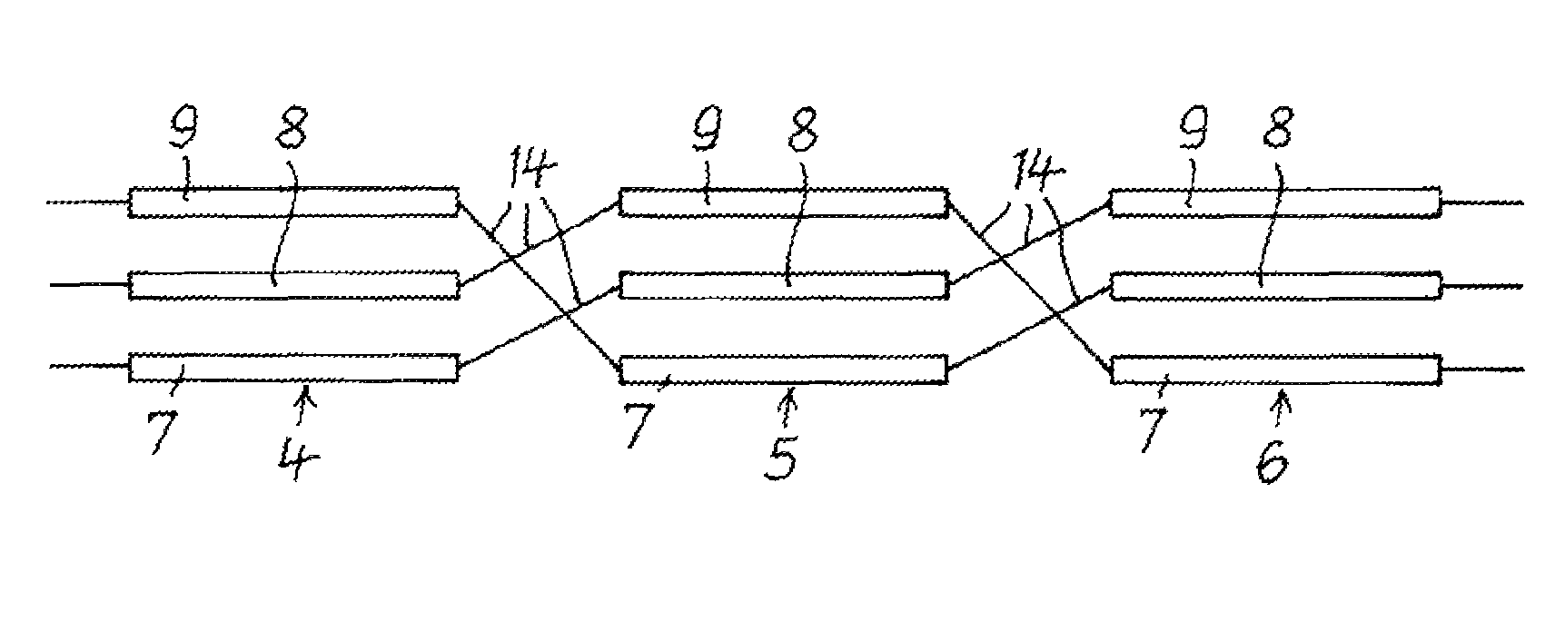
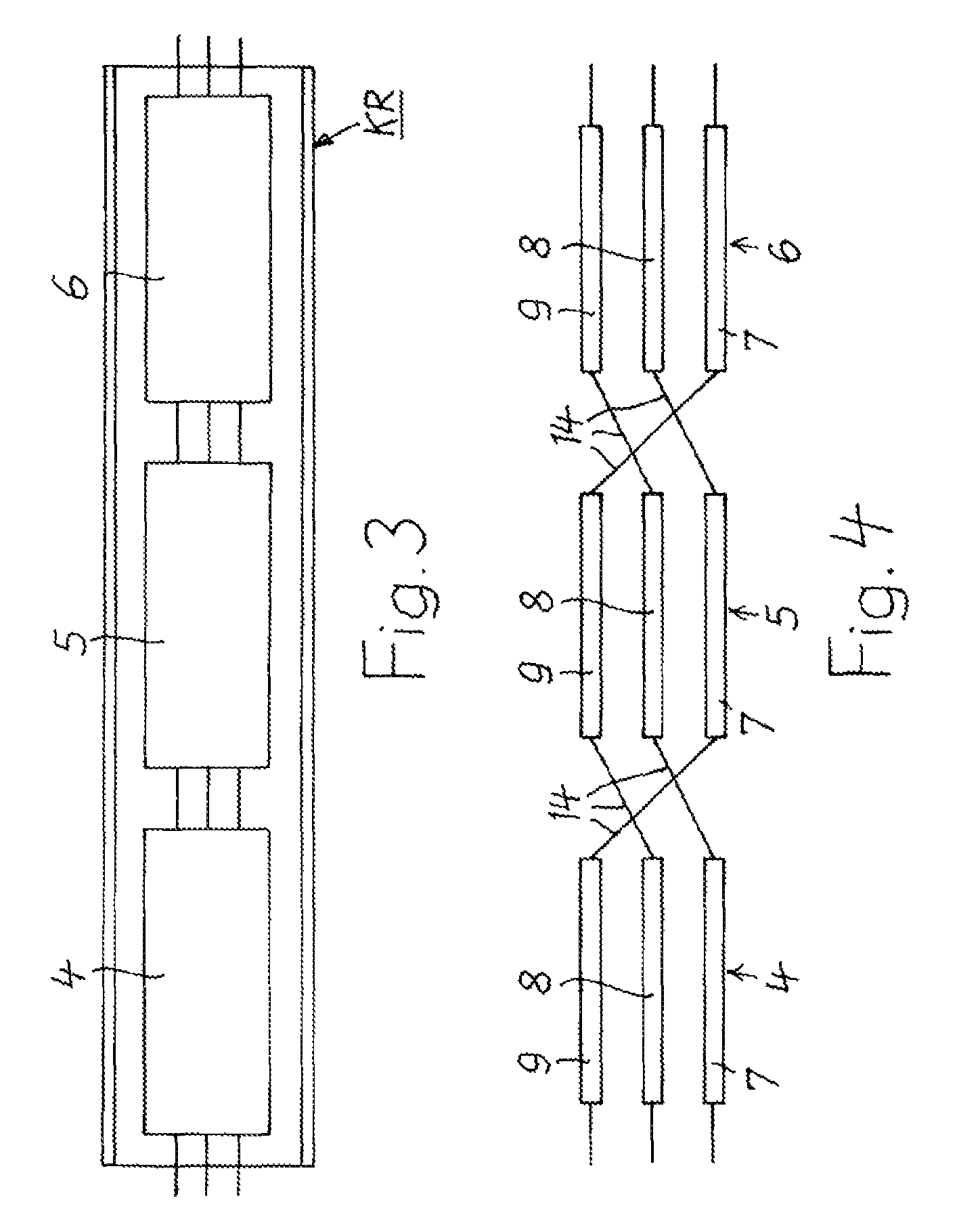
[0020]The arrangement according to the invention will be explained in the following text for three (n=3) components each having three superconducting phase conductors. With an appropriate design, two or more units, each having three such components, could also be accommodated in one cryostat.

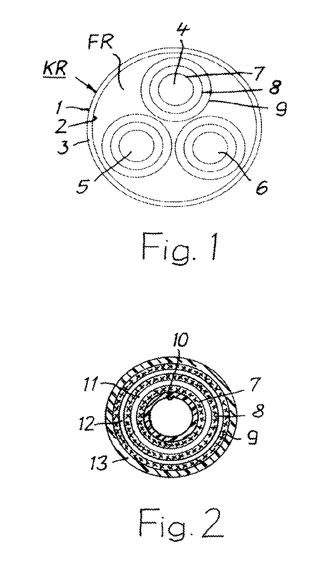
[0021]FIG. 1 shows a cryostat KR comprising two metallic tubes 1 and 2 which are arranged coaxially with respect to one another. Vacuum insulation 3 is located between the tubes 1 and 2, which may also be corrugated transversely with respect to their longitudinal direction. The cryostat KR surrounds a free space FR for a coolant to pass through, in which free space FR three components 4, 5 and 6 are arranged, which each have three phase conductors 7, 8 and 9, which are insulated from one another and are arranged concentrically with respect to one another.

[0022]The superconducting phase conductors 7, 8 and 9 advantageously comprise ribbons composed of ReBCO, to be precise preferably YBCO. The inn...


PUM

PropertyMeasurementUnit
temperaturesaaaaaaaaaa
currentaaaaaaaaaa

Abstract

An arrangement for current limiting is specified, using components (4, 5, 6) composed of a superconducting material which are arranged in a cryostat (KR) which comprises two metallic tubes (1, 2) which are arranged concentrically with respect to one another and between which vacuum insulation (3) is fitted, and which cryostat surrounds a free space (FR) for a coolant to pass through. The components (4, 5, 6) each comprise three phase conductors (7, 8, 9) composed of a superconducting material based on rare earths (ReBCO), which are arranged insulated from one another and concentrically with respect to one another. “n” components (4, 5, 6) are arranged in the cryostat (KR) and their phase conductors are cyclically electrically conductively connected to one another such that the inner phase conductor (7) of each component is connected to the centre phase conductor (8) of a second component, and this centre phase conductor (8) is connected to the outer phase conductor (9) of the third component, where n=3 or an integer multiple of 3.

Description

RELATED APPLICATIONS[0001]This application claims the benefit of priority from European Patent Application No. 09290181.8, filed on Mar. 13, 2009, the entirety of which is incorporated by reference.BACKGROUND[0002]1. Field of the Invention[0003]The invention relates to an arrangement for current limiting, using components composed of a superconducting material which are arranged in a cryostat which comprises two metallic tubes which are arranged concentrically with respect to one another and between which vacuum insulation is fitted, and which cryostat surrounds a free space for a coolant to pass through (EP 1 681 731 A1).[0004]2. Description of Related Art[0005]By way of example, superconducting materials are used as conductors in cables which are used for electrical power transmission. In modern technology, the superconducting material comprises a composite material which contains ceramic material, which changes to the superconducting state at sufficiently low temperatures. The el...

Claims


Application Information

Patent Timeline
Patent Type & Authority Patents(United States)
IPC IPC(8): H01B11/02
CPCH01B12/06H01L39/16H02G15/34Y02E40/648Y02E40/642Y02E40/60H10N60/30
Inventor STEMMLE, MARKSOIKA, RAINER
Owner NEXANS
Why Eureka
Try Eureka