Signal transmission line structure and display panel

A signal transmission line, signal transmission technology, applied to static indicators, instruments, etc., can solve the problems of reducing input signal impedance, impedance imbalance, large input signal impedance, etc., and achieve the effect of solving display problems

Active Publication Date: 2020-10-16
TCL CHINA STAR OPTOELECTRONICS TECH CO LTD
View PDF16 Cites 1 Cited by
  • Summary
  • Abstract
  • Description
  • Claims
  • Application Information

AI Technical Summary

Problems solved by technology

[0006] The present application provides a signal transmission line structure, which solves the problem of relatively large impedance of each input signal transmitted in the display panel
[0007] The present application provides a display panel, which at least includes the above-mentioned signal transmission line structure, which can reduce the impedance of the input signal transmitted in the display panel, thereby solving the impedance imbalance caused by the transmission of each input signal in the display panel, The resulting display problems such as equally spaced horizontal lines

Method used


Image

  • Signal transmission line structure and display panel
  • Signal transmission line structure and display panel
  • Signal transmission line structure and display panel

Examples


Embodiment Construction

[0025] The technical solutions in the embodiments of the present application will be clearly and completely described below in conjunction with the drawings in the embodiments of the present application. Apparently, the described embodiments are only some of the embodiments of this application, not all of them. Based on the embodiments in this application, all other embodiments obtained by those skilled in the art without making creative efforts belong to the scope of protection of this application.

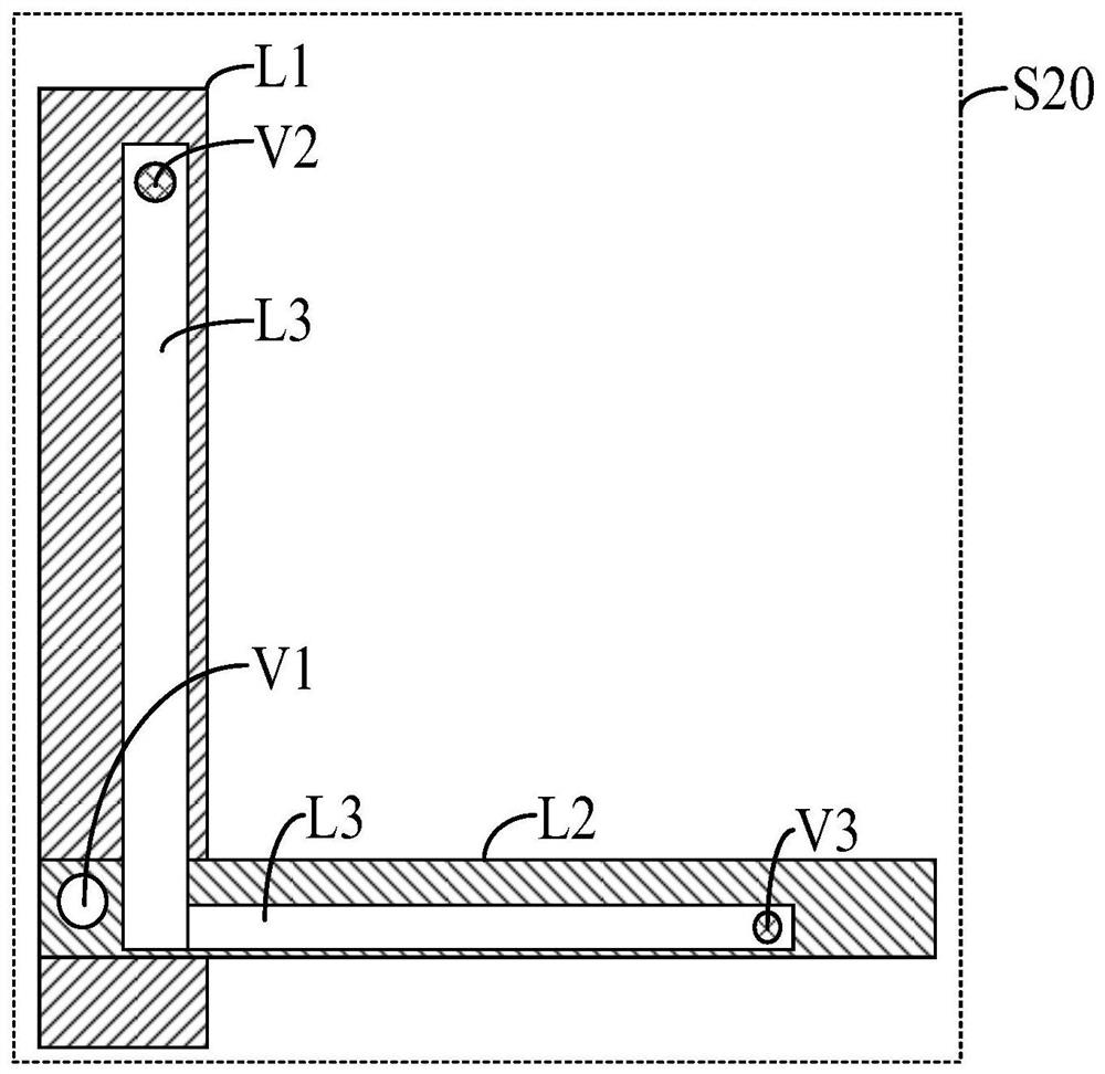
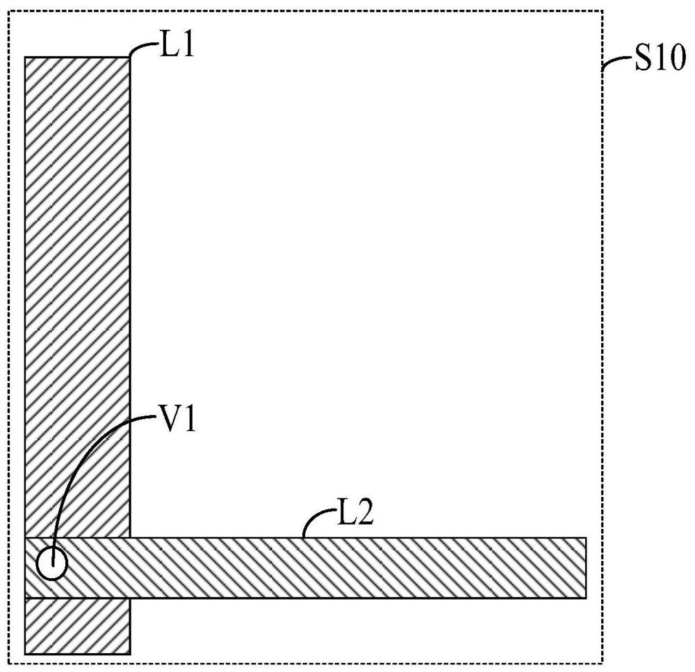
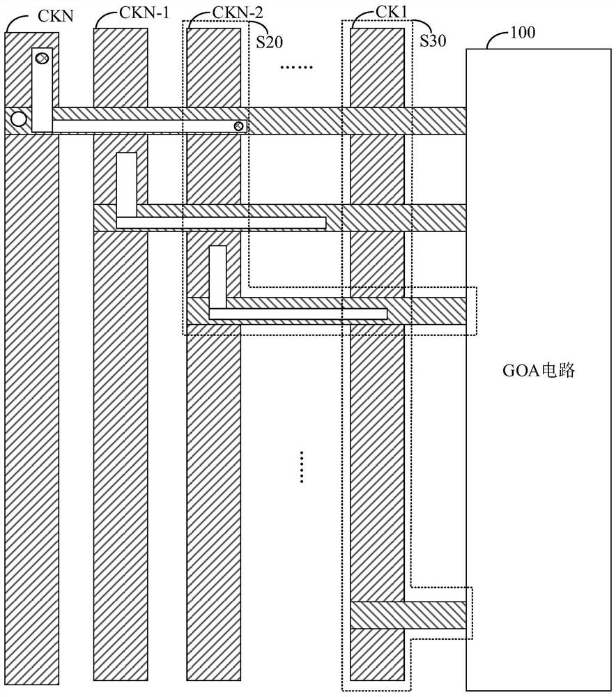
[0026] Such as figure 1 with figure 2 As shown, this embodiment provides a signal transmission line structure, the signal transmission line structure includes: a first signal transmission line L1 located in the first metal layer; a second signal transmission line L2 located in the second metal layer; a first via V1 located in The first metal layer and the second metal layer are used to electrically connect the first signal transmission line L1 and the second signal transmissio...


PUM


Abstract

The invention discloses a signal transmission line structure and a display panel. The signal transmission line structure comprises: a first signal transmission line; a second signal transmission line;and a third signal transmission line. The third signal transmission line is connected with the first signal transmission channel in parallel, so that a second signal transmission channel with lower impedance can be formed; the display panel is provided with the signal transmission line structure, and impedance borne by transmission of all input signals in the display panel can be reduced to be balanced.

Description

technical field [0001] The present application relates to the field of display technology, in particular to the field of GOA drive technology, and in particular to a signal transmission line structure and a display panel. Background technique [0002] At present, most gate driving circuits of display panels use GOA (gate on array) circuits. The GOA circuit includes an input signal and multiple cascaded GOA unit circuits, and the input signal may include square wave signals such as scan start signals and clock signals. [0003] These square wave signals are transmitted from the outside of the display panel to the GOA circuit through corresponding wires, and the paths of these wires are different, resulting in different impedances of each wire, resulting in different input signals. , especially the impedance delay of each clock signal is different. [0004] The difference in impedance of the clock signal may easily cause a difference in the rising edge and / or falling edge of...

Claims


Application Information

Patent Timeline
Patent Type & Authority Applications(China)
IPC IPC(8): G09G3/36G09G3/20
CPCG09G3/2092G09G3/3611
Inventor 陈亚妮
Owner TCL CHINA STAR OPTOELECTRONICS TECH CO LTD
Why Eureka
Try Eureka