Lamintated clamp for a tire changer

a technology for a tire changer and a clamping surface, which is applied in the direction of wheel mounting apparatus, instruments, and static/dynamic balance measurement, etc., can solve the problems of accumulated road grime and oil on the tapered surface, the amount of rotational slippage of the rim, and possible damage to the rim

Active Publication Date: 2013-01-08
HENNESSY IND
View PDF7 Cites 15 Cited by
  • Summary
  • Abstract
  • Description
  • Claims
  • Application Information

AI Technical Summary

Benefits of technology

[0010]According to one aspect, the present invention provides a clamp for use in securing a wheel rim on a rim-holding tire changer. The clamp includes a base portion, at least one gripping plate secured to the base portion, at least one support plate secured to the base portion such that the at least one gripping plate is disposed b

Problems solved by technology

With existing rim-holding tire changers, it is not uncommon for there to be some amount of rotational slippage of the rim relative to the clamps during the mount/demount procedure.
The rotational slippage is undesirable in that it can lead to possible damage to the rim.
In many cases, road grime and oil may have accumulated on this tapered surface.
Because the force used to hold the rim in place is based on a frictional connection, the road grime and oil may cause the wheel to move upward and off the clamps.
In addition, the increased force required to remove performance type tires from th

Method used


Image

  • Lamintated clamp for a tire changer
  • Lamintated clamp for a tire changer
  • Lamintated clamp for a tire changer

Examples


Embodiment Construction

[0025]Reference will now be made in detail to presently preferred embodiments of the invention, one or more examples of which are illustrated in the accompanying drawings. Each example is provided by way of explanation, not limitation, of the invention. In fact, it will be apparent to those skilled in the art that modifications and variations can be made in the present invention without departing from the scope and spirit thereof. For instance, features illustrated or described as part of one embodiment may be used on another embodiment to yield a still further embodiment. Thus, it is intended that the present invention covers such modifications and variations as come within the scope of the appended claims and their equivalents.

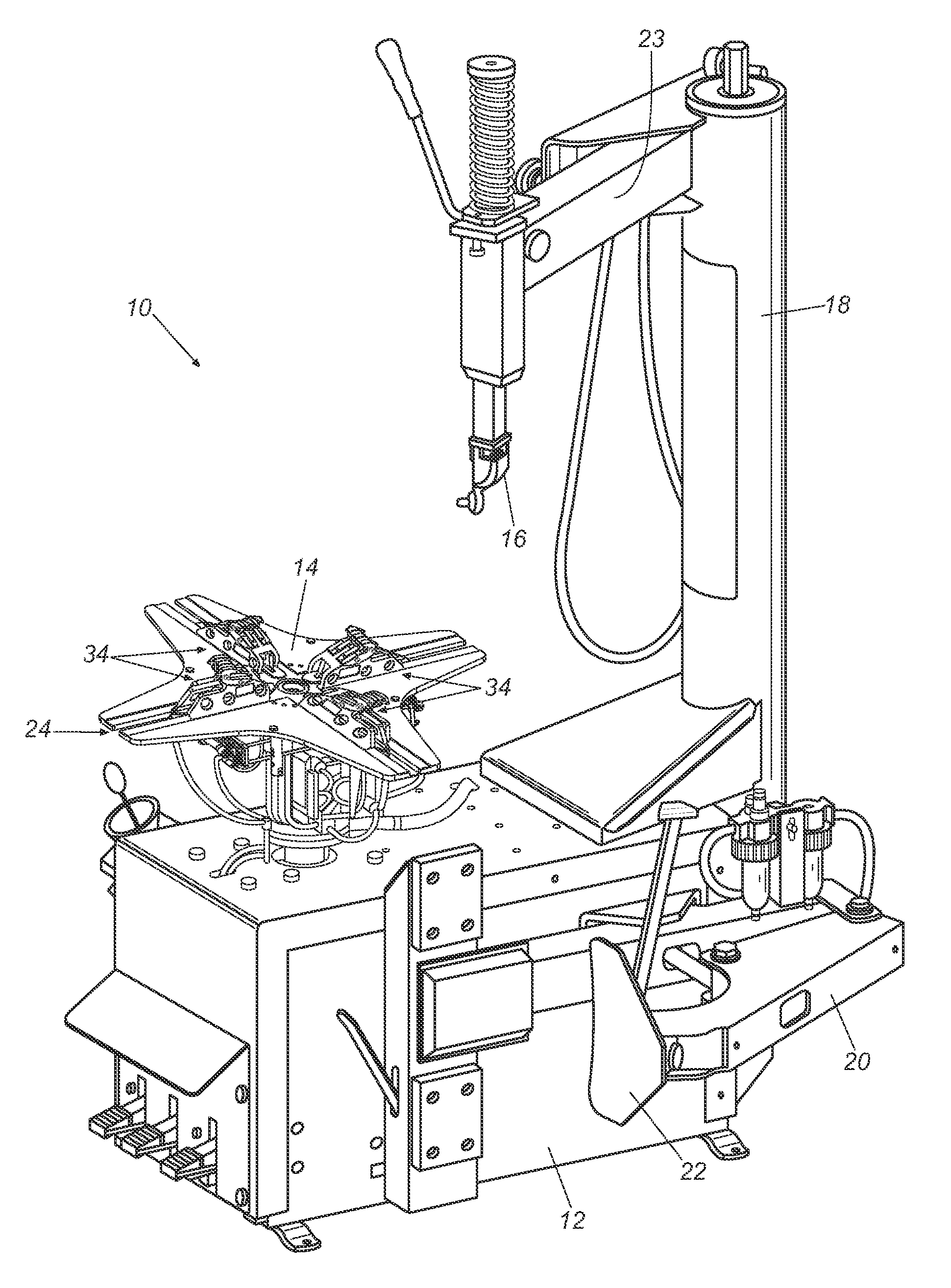
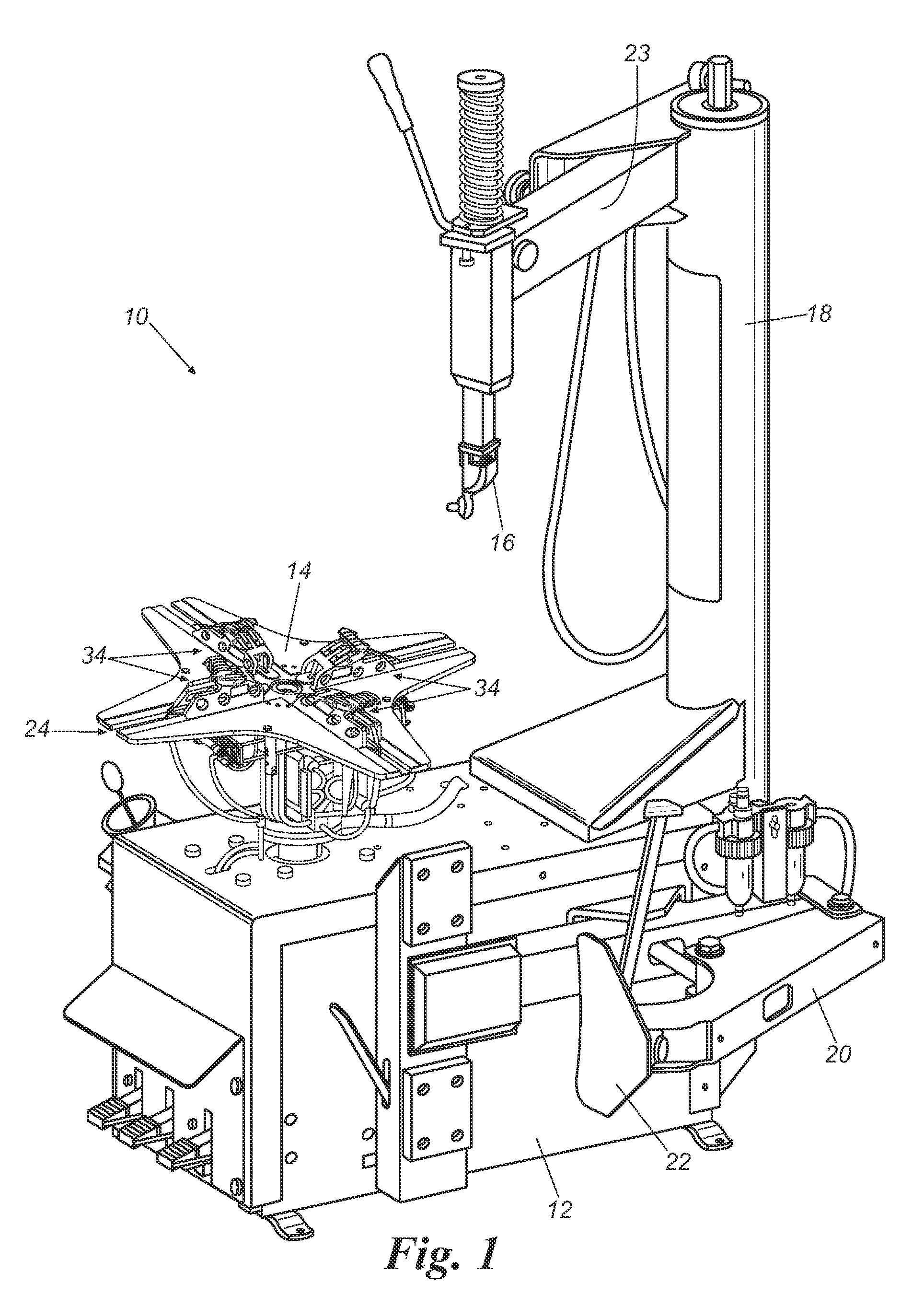
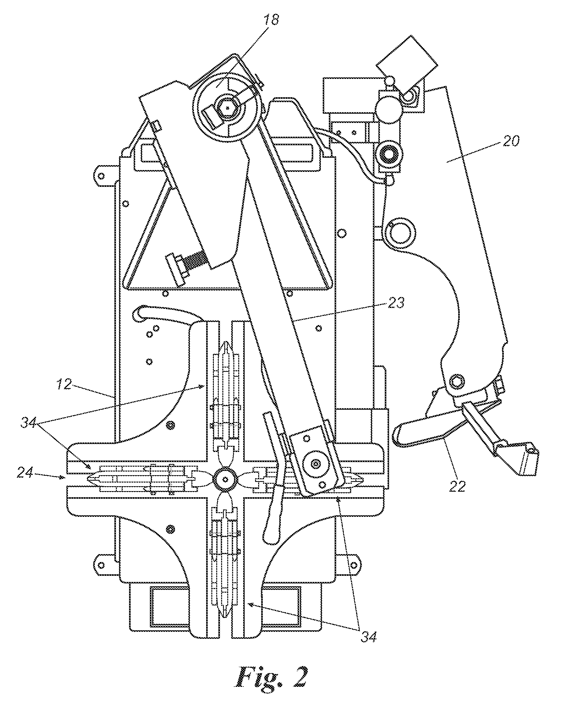
[0026]Referring to FIGS. 1 through 3, a rim-holding tire changer 10 includes a chassis 12, a rotatable tabletop 14, a mount / demount head 16, a tower 18, and a carrier arm 20 that supports a bead loosener shoe 22. Head 16 is located at the distal end of a swi...


PUM


Abstract

A clamp for securing a wheel with a rim on a rim-holding tire changer. The clamp includes a base portion, a gripping plate secured to the base portion, and a support plate secured to the base portion such that the gripping plate is disposed between the base portion and the support plate. The gripping plate is configured with a first portion for engaging the rim of a wheel and the support plate is configured with a first portion to engage the rim of the wheel.

Description

CLAIM OF PRIORITY[0001]This application claims priority to U.S. Provisional Patent Application No. 60 / 983,430, filed on Oct. 29, 2007, the entire disclosure of which is incorporated by reference herein.FIELD OF THE INVENTION[0002]The present invention relates generally to tire changers. More particularly, the present invention relates to a laminated clamp for use with a rim-holding style tire changer.BACKGROUND OF THE INVENTION[0003]Rim-holding style tire changers are known. A typical rim-holding tire changer includes a chassis having a rotatable tabletop and a tower. A combination mount / demount head is supported by the tower. For example, the mount / demount head may be located at the distal end of a pivotable swing arm attached near the top of the tower. In other cases, the tower itself is tiltable toward and away from the tabletop. Various rim-holding style tire changers are manufactured by Hennessy Industries, Inc. and marketed under the trademark COATS®.[0004]During a typical tir...

Claims


Application Information

Patent Timeline
IPC IPC(8): B60B30/06
CPCB60B30/06B60C25/0539
Inventor CUNNINGHAM, CHARLES L.
Owner HENNESSY IND
Why Eureka
Try Eureka