Device for controlling the drive of a reel

a technology of drive and reel, applied in the direction of information storage, material accumulating device, yarn, etc., to achieve the effect of small tension fluctuation

Active Publication Date: 2013-02-26
WAFIOS AKTIENGES
View PDF7 Cites 9 Cited by
  • Summary
  • Abstract
  • Description
  • Claims
  • Application Information

AI Technical Summary

Benefits of technology

[0014]Due to the fact that the preset rotation speed-time profile of the reel in comparison to the velocity-time profile of the feed velocity of the wire infeed is started set forward by a preset time interval by the control of the reel drive, i.e., the reel drive already sets in at a point in time when the control unit of the processing machine has not yet started the velocity-time profile of the feed velocity of the infeed but which takes place rather time-delayed only after startup of the reel drive, it can basically be achieved that the reel will already have released some wire before the startup of the infeed rollers of the wire infeed of the processing machine, and that said wire is now already available at the entrance of the infeed rollers of the infeed at the time of their start-up and, therefore, does not have to be pulled by the wire infeed rollers from the downstream-positioned coil under build-up of tension peaks. Due to the fact that the preset rotation speed-time profile for the reel drive is adjusted to the preset velocity-time profile of the drive of the infeed rollers at the wire infeed of the processing machine, it is possible to invariably take into account any changes in the curve of the wire infeed speed at the wire infeed earlier through an appropriate change in the rotation speed-time profile of the reel. For example, even with high dynamic processing machines, through the appropriate choice of the time advance of the drive of the reel, the quick speed changes on the reel side of the infeed rollers of the wire infeed can be compensated, and the larger amounts of wire required with quick accelerations or decelerations of the infeed speed of the infeed rollers can be built up in due time or their deceleration taken into account in due time. This is also important because the great weight of the wire coils only allows for significantly more limited accelerations and / or decelerations of the rotation speed of the reel (and therefore the wire to be released) than is possible on the side of the infeed rollers of the wire infeed.
[0025]Since the rotation speed-time profile of the reel in this embodiment consistently shows evenly occurring vibrations during the ongoing manufacturing of the same workpieces, a particularly simple control of such a reel drive and, overall, a particularly high processing speed can hereby be achieved.

Problems solved by technology

However, in this solution, the rotation speed-time profile for the reel control is preset from the start, so that no control takes place as a reaction to a prior behavior of the infeed movement of the wire infeed.

Method used


Image

  • Device for controlling the drive of a reel
  • Device for controlling the drive of a reel
  • Device for controlling the drive of a reel

Examples


Embodiment Construction

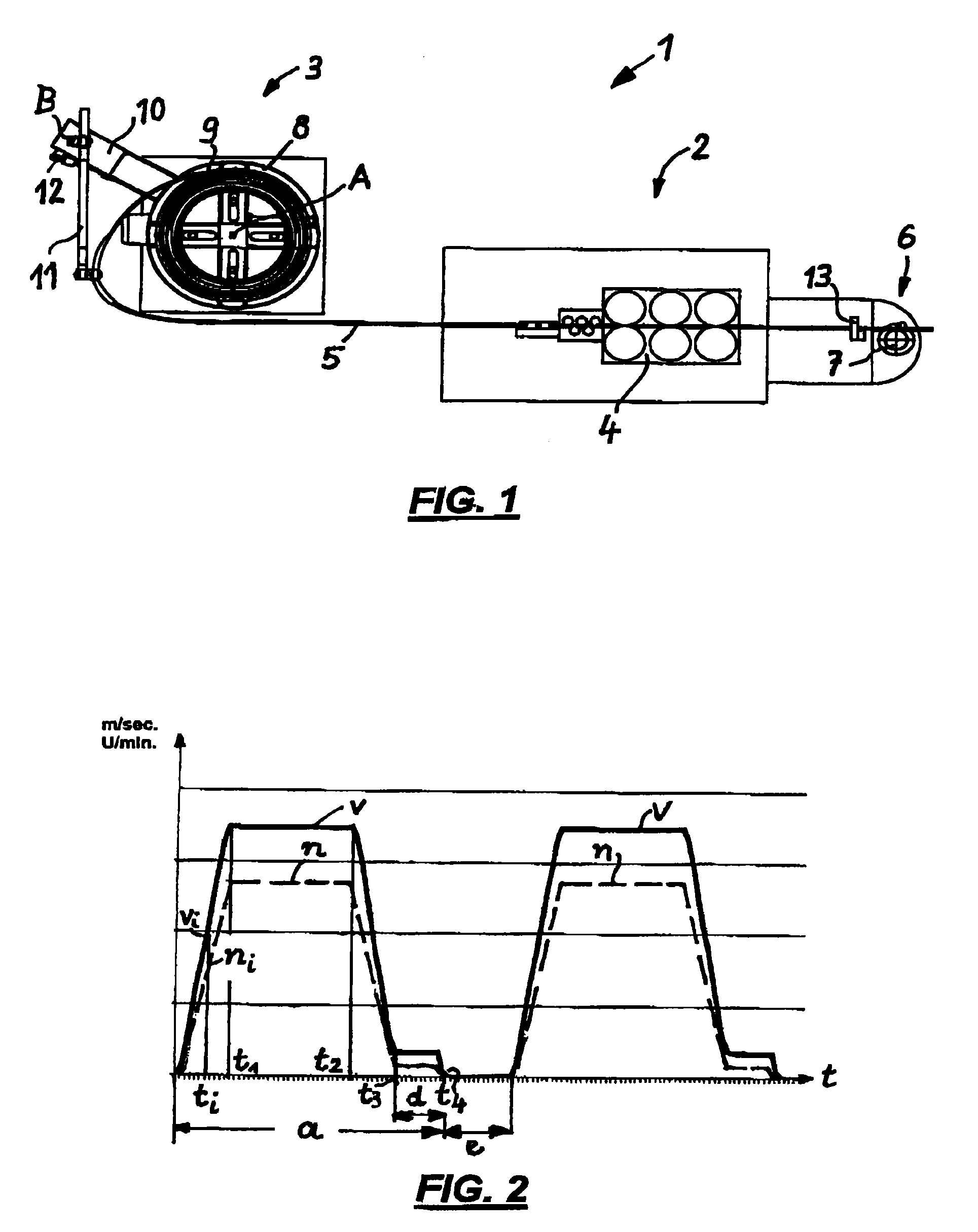
[0033]FIG. 1 shows a top view of a wire bending installation 1 which consists of a processing machine 2 (here: a wire bending machine) and a reel 3. The processing machine 2 contains a feed or infeed device 4, e.g., a roller infeed, which pulls the wire 5 from the reel 3 and feeds it to a processing area 6, in the drawing a bending head 7, of the processing machine 2.

[0034]The reel 3 is equipped with a drive (not shown), which includes a coil holder 8 and which rotates the reel as well as the overlying wire coil 9 around a rotation axis A in order for the coil material to roll off.

[0035]Furthermore, reel 3 exhibits an attached cantilever 10, which holds a swivel arm 11, which in turn is swiveling around the axis B and which is controlled by a control unit 12 in such a way that as constant as possible a tensile force exists on the wire 5 between the infeed 4 and the reel 3. Via the size and the direction of the deflection of the deflection arm 11, the rotation speed of the reel 3 can...


PUM

PropertyMeasurementUnit
velocityaaaaaaaaaa
rotation speedaaaaaaaaaa
speedaaaaaaaaaa

Abstract

With a device for controlling the drive of a reel, with a wire supply in the form of a coil of said wire supply, from which the wire, through interposition of a tensioning device, which is spring-pretensioned in one deflection direction and effective up to a maximum deflection, for approximated stabilization of the wire tension of a feed installation of the wire infeed of a downstream positioned wire processing machine, the velocity curve of the feed rate of the wire infeed in accordance with a preset velocity-time profile is controlled by a control unit of the wire processing machine, and whereby the curve of the rotation speed of the reel in accordance with a preset rotation speed-time profile is controlled by the drive control of the reel, whereby the drive control of the reel sets the rotation speed-time profile of the reel, with regard to the velocity-time profile of the feed rate, forward by a preset time interval.

Description

[0001]This application claims priority to German Patent Application No. 10 2010 012 263.7 filed on Mar. 22, 2010, which is incorporated herein by reference in its entirety.FIELD OF THE INVENTION[0002]The present invention relates to a device for providing wire and controlling the drive of a reel with a wire supply in which the wire is spring-pretensioned for approximated stabilization of the wire tension of a feed installation of the wire infeed of a downstream positioned wire processing machine.BACKGROUND OF THE INVENTION[0003]Processing machines for processing coil material, such as spring machines, bending machines, nailing machines, leveling machines, etc. operate, as a rule, together with reels, which hold a supply of coil material, such as wire. Starting with said coil, e.g., the wire is fed to the processing machine, which is downstream of the reel. The reel is usually driven at a constant rotation speed, whereby the rotation speed of the reel determines how much wire is unwo...

Claims


Application Information

Patent Timeline
Patent Type & Authority Patents(United States)
IPC IPC(8): B21C47/16B21C49/00B21F23/00B65H51/30B65H59/38
CPCB21C47/16B21C49/00B21F23/00B65H51/10B65H51/30B65H59/387
Inventor FRIES, STEFANSTEINHILBER, WERNERLENGERER, HELMUT
Owner WAFIOS AKTIENGES
Why Eureka
Try Eureka