Control device for rolling stock drive device

一种驱动装置、控制装置的技术,应用在传动装置控制、通用动力装置的多个不同原动机的布置、动力装置等方向,能够解决发热量增大、时间长等问题,达到减少变速次数、减少能量损失、提高能量效率的效果

Active Publication Date: 2015-05-20
AISIN AW CO LTD
View PDF8 Cites 7 Cited by
  • Summary
  • Abstract
  • Description
  • Claims
  • Application Information

AI Technical Summary

Problems solved by technology

However, as mentioned above, skip shifting has the problem that the time required for shifting is long, and the amount of heat generated by the engagement element responsible for releasing the rotational braking force during the inertia phase increases.

Method used


Image

  • Control device for rolling stock drive device
  • Control device for rolling stock drive device
  • Control device for rolling stock drive device

Examples


no. 1 approach >

[0045]

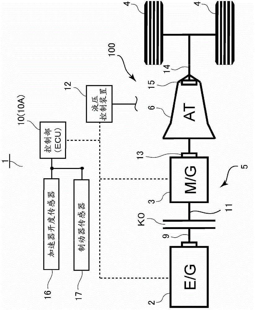
[0046] Such as figure 1 as well as figure 2 As shown, a hybrid vehicle (hereinafter, simply referred to as a vehicle) 1 has a rotating electric machine (hereinafter, referred to as a motor generator or simply a motor) 3 as a drive source in addition to an internal combustion engine 2 . The hybrid drive device 100 as a vehicle drive device constituting the drive train of the vehicle 1 is a single-motor type hybrid drive device, and includes a transmission mechanism 6 arranged on a transmission path between the internal combustion engine 2 and the wheels 4, and The input unit 5 between the transmission mechanism 6 and the internal combustion engine 2 is constituted.
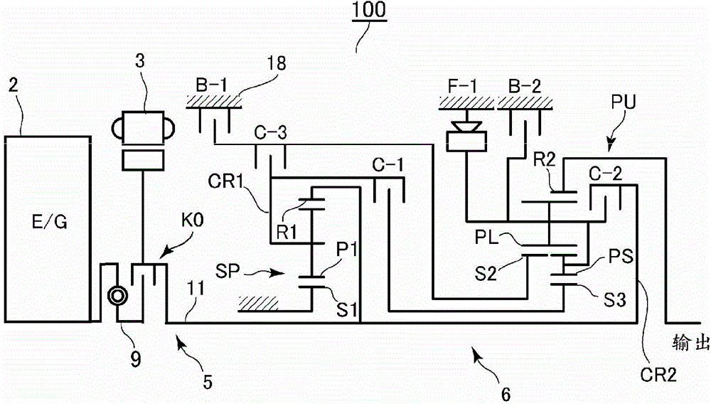
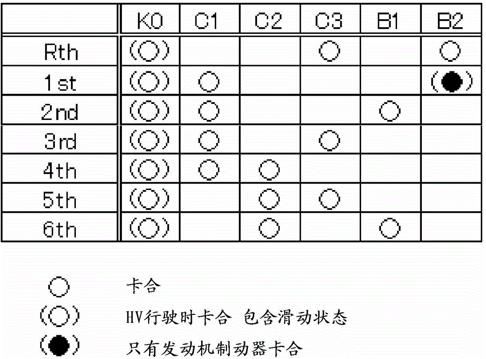
[0047] Speed ​​change mechanism 6 such as figure 2 Shown has a plurality of engagement elements (more specifically, a plurality of frictional engagement elements) C-1 to C-3, B-1, B-2, F-1, and the card through these plurality of engagement elements A multi-speed automatic transmission (stepped auto...

no. 2 approach >

[0096] Next, according to Figure 9 to Figure 11 A vehicle control device according to a second embodiment of the present invention will be described. In addition, the second embodiment is different in that the estimated temperature of the frictional engagement element at the time of shifting is calculated, and whether the skip shift can be performed is determined based on whether the estimated temperature is higher than the allowable temperature. Therefore, in the following description, only the points of difference from the above-mentioned first embodiment will be described, and descriptions of other parts will be omitted.

[0097] Figure 9 It is a graph showing the transition of the estimated temperature of the main body side frictional engagement element while the vehicle is running. exist Figure 9 It can be seen that the frictional engagement element on the main body side is engaged and switched at time t1-t2 and time t3-t4, and generates heat due to transmission of ...

no. 3 approach >

[0106] In the above-mentioned second embodiment, whether or not the skip shift can be performed is determined based on all the requirements of the calorific value, the estimated temperature, and the shift time. However, for example, the skip shift may be judged based only on the calorific value. Can it be implemented. Of course, it is also possible to determine whether skip shifting can be performed based only on the estimated temperature requirement, and it is also possible to determine whether skip shifting can be performed based only on these calorific value requirements and the estimated temperature requirement.

[0107] In addition, in the above-mentioned first to third embodiments, a hybrid drive device has been described as an example of a drive device for a vehicle. However, an engine is not necessarily required as a drive source. As long as it is a vehicle with a rotary electric machine on the input side of the transmission mechanism, The present invention can be appl...


PUM


Abstract

A control device (10) for a rolling stock drive device (100) carries out the following: when shifting a transmission mechanism (6) in a state where a rotary electric machine (3) is regenerated, predicts a heat generation amount generated by an engagement element that switches grip when shifting, in a case where a target gear stage after shifting is separated from the current gear stage by numerous stages; determines from the predicted heat generation amount whether there is jump shift that jumps a gear stage that can be carried out between the current gear stage and the target gear stage; and in a case where there is a jump shift that can be carried out, controls the transmission mechanism (6) so that while the jump shift is carried out, shifting is carried out from the current gear stage to the target gear stage.

Description

technical field [0001] The present invention relates to a control device for a vehicle drive device in which a rotary electric machine is disposed on an input side of a transmission mechanism. Background technique [0002] In recent years, as represented by vehicles such as hybrid vehicles and electric vehicles, vehicles that have a rotating electrical machine as a drive source, and regenerate the rotating electrical machine to convert the kinetic energy of the vehicle into electrical energy and recover it to improve energy efficiency have become popular. develop. [0003] Conventionally, in order to obtain a sufficient amount of regeneration by the above-mentioned rotating electric machine, for example, it is described in Japanese Patent Application Laid-Open No. 2008-94253 that a rotating electric machine (motor generator) is disposed between the engine and the stepped automatic transmission. In a hybrid vehicle, the stepped automatic transmission is skipped and downshift...

Claims


Application Information

Patent Timeline
Patent Type & Authority Applications(China)
IPC IPC(8): F16H61/16B60W30/186B60W20/00
CPCB60K2006/4825B60W10/115B60W20/30B60W30/186B60W2710/1005F16H61/16F16H61/21F16H2059/725F16H2306/14Y02T10/62B60W20/11B60W20/14Y10S903/945F16H59/72
Inventor 津田耕平小野内友宏草部圭一朗
Owner AISIN AW CO LTD
Why Eureka
Try Eureka