
Shift position detection apparatus for variable speed gear

a technology of variable speed gear and shift position detection, which is applied in the direction of mechanical control devices, instruments, process and machine control, etc., can solve the problems of complicated and easy scale increase of the configuration of the shift position detection apparatus, and achieve the effect of suppressing reducing the length of the shift sha

Active Publication Date: 2006-09-12
HONDA MOTOR CO LTD
View PDF11 Cites 8 Cited by
  • Summary
  • Abstract
  • Description
  • Claims
  • Application Information

AI Technical Summary

Benefits of technology

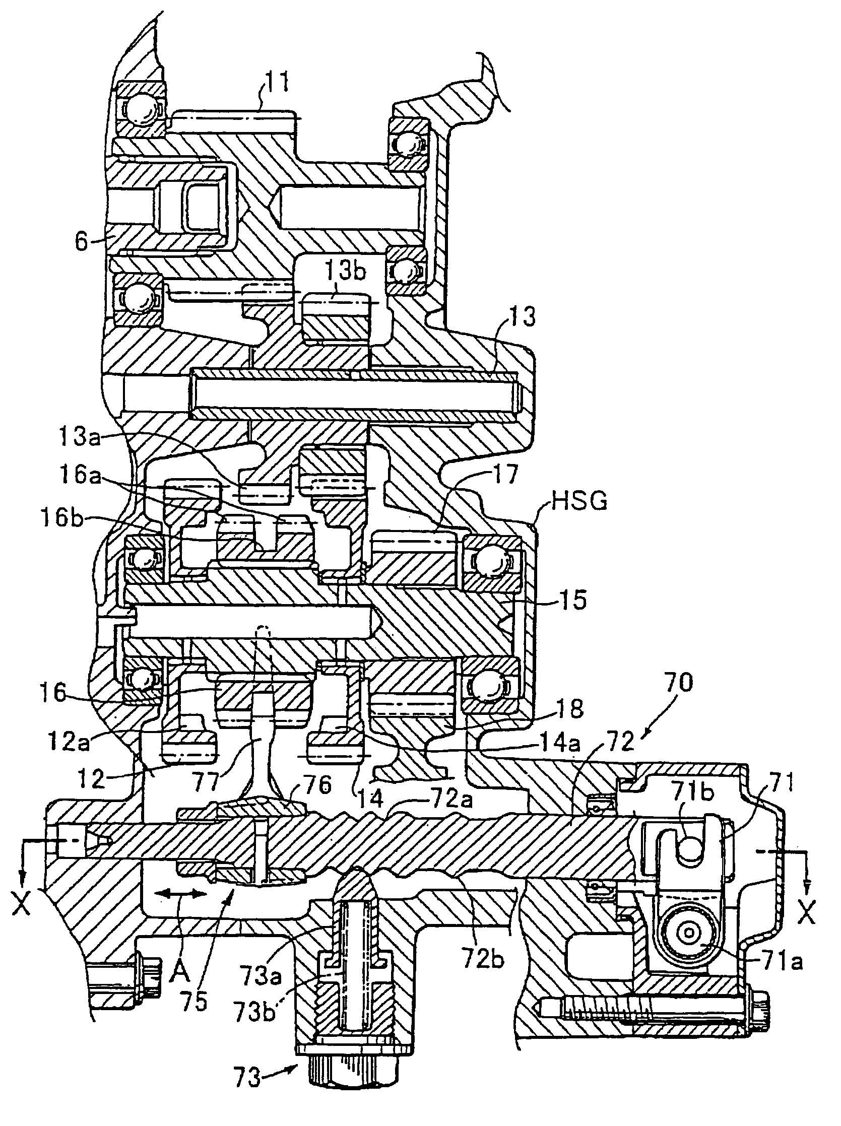
[0011]With the shift position detection apparatus according to the present invention having such a configuration as described above, at least two of the shift detection portions are disposed at different positions on the substantially same plane perpendicular to the axis of the shift shaft, that is, at the same position in the axial direction. Therefore, at least two shift detection portions and the position sensors opposing to them are disposed at positions on the substantially same plane perpendicular to the axis, that is, at the same position in the axial direction. Consequently, the dimension of the variable speed gear in the axial direction is not increased and can be miniaturized and made compact.
[0013]When such a configuration as described above is employed, the length of the shift shaft can be suppressed thereby miniaturizing and making a compact variable speed gear. Particularly where at least two shift detection portions are provided on the outer periphery of the cylindrical portion of the shift fork, the number of shift detection portions to be provided on the shift shaft can be reduced to reduce the length of the shift shaft. Consequently, the variable speed gear can be further miniaturized and made compact.

Problems solved by technology

Therefore, the variable speed gear encounters a problem wherein the configuration of the shift position detection apparatus is liable to have an increase in scale and be complicated.

Method used


Image

  • Shift position detection apparatus for variable speed gear
  • Shift position detection apparatus for variable speed gear
  • Shift position detection apparatus for variable speed gear

Examples


Embodiment Construction

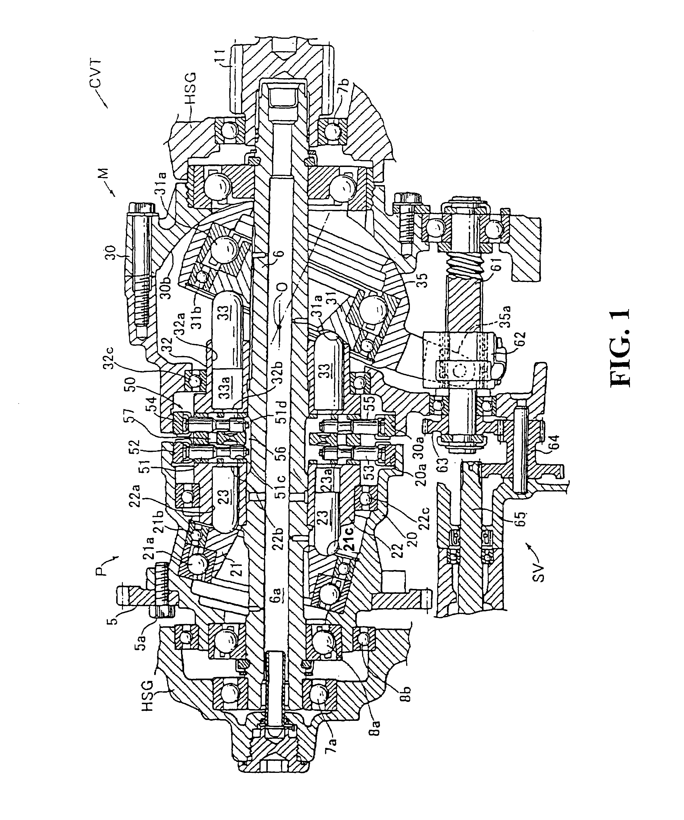
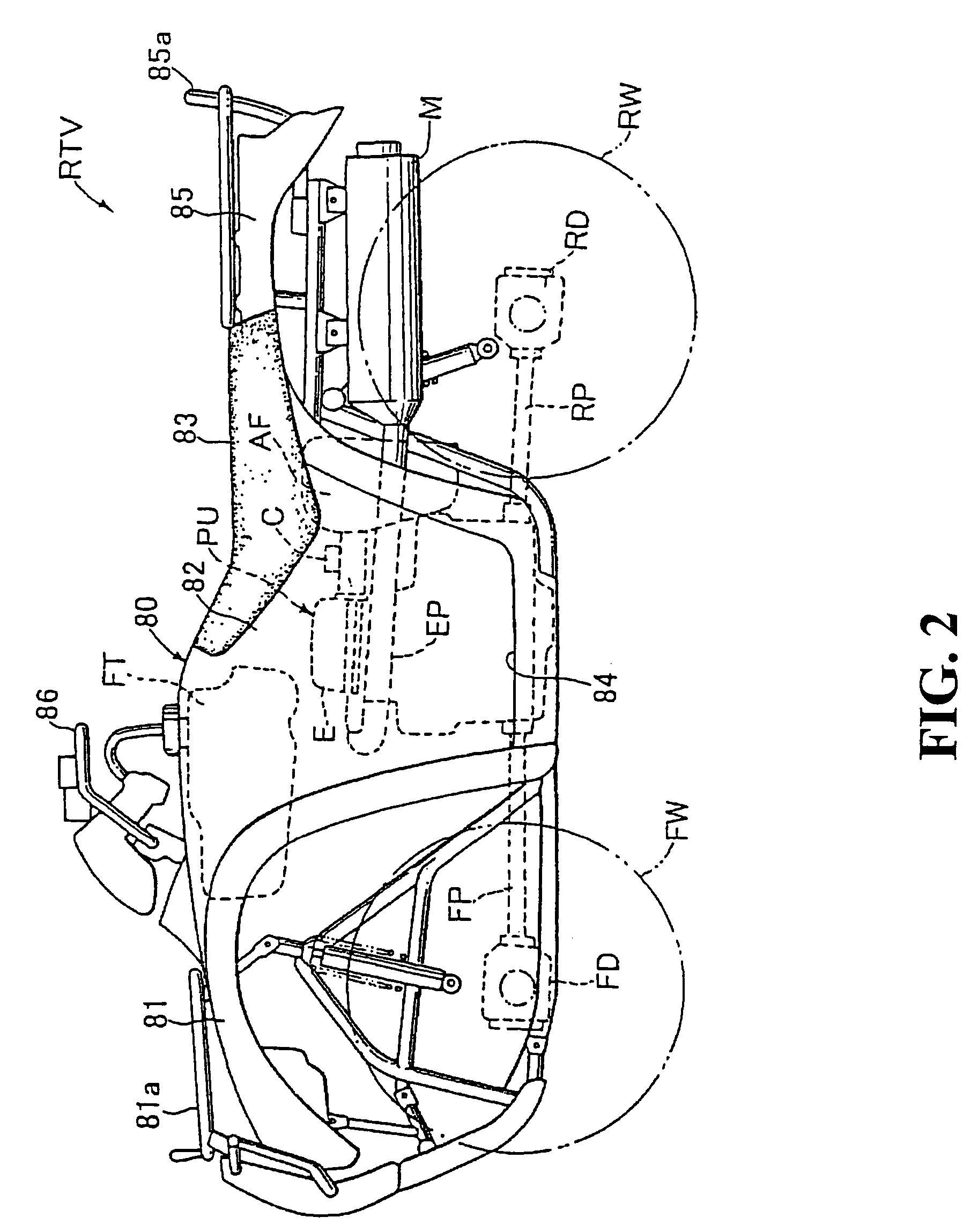
[0026]In the following, a preferred embodiment of the present invention is described with reference to the drawings. FIGS. 2 to 4 show a vehicle RTV for traveling on an irregular ground which includes a hydraulic continuously variable transmission having a variable speed gear according to the present invention. The vehicle RTV includes a power unit PU built in a vehicle body 80 having a frame structure in the inside thereof and left and right front and rear wheels FW and RW which receive and are driven by output power of the power unit PU. The vehicle body 80 includes a front fender section 81 having a front guard 81a positioned at a front portion of the vehicle body. A saddle section 82 is provided that is swollen upwardly at a mid portion of the vehicle body and extends forwardly and rearwardly. Left and right step sections 84, 84 are formed to extend leftward and rightward at left and right lower portions of the saddle section 82. A rear fender section 85 includes a rear guard 85...


PUM


Abstract

A shift position detection apparatus for a variable speed gear wherein a shift shaft is moved in an axial direction to perform a speed changing operation. A variable speed gear includes a clutch sleeve disposed for movement in an axial direction on a counter shaft with a shift shaft disposed so as to extend in parallel to the counter shaft. A shift fork is coupled and attached to the shift shaft and has an end engaged with the clutch sleeve. The clutch sleeve is moved in the axial direction through the shift fork to select a shift position. A shift position detection apparatus includes F, R and N shift detection portions provided on the shift fork. The F shift detection portion and the R shift detection portion are spaced by approximately 60 degrees in a circumferential direction on substantially the same plane perpendicular to the axis of a cylindrical portion.

Description

CROSS-REFERENCE TO RELATED APPLICATIONS[0001]The present application claims priority under 35 USC 119 to Japanese Patent Application No. 2003-120449 filed on Apr. 24, 2003 the entire contents thereof is hereby incorporated by reference.BACKGROUND OF THE INVENTION[0002]1. Field of the Invention[0003]This invention relates to a variable speed gear wherein a shift shaft and a shift fork are moved in an axial direction in response to a shift movement of a shift operation member to move a clutch member on a power transmission shaft and to select a shift position.[0004]2. Description of Background Art[0005]Various types of variable speed gears for use with a gear type variable speed mechanism which includes a plurality of gear trains are conventionally known for selecting one of the gear trains. As a speed change mechanism for use with a variable speed gear of the type described, for example, a speed change mechanism of the selective sliding type is provided wherein a power transmission g...

Claims


Application Information

Patent Timeline
Patent Type & Authority Patents(United States)
IPC IPC(8): F16H59/00F16H61/00F16H63/00F16H63/30F16H59/70
CPCF16H59/70Y10T74/2014Y10T74/19251Y10T74/1926Y10T74/20183
Inventor ITO, KATSUHIKOKEYAKI, SHINICHIRO
Owner HONDA MOTOR CO LTD
Learn More