Webbing take-up device

a take-up device and webbing technology, applied in the direction of buckles, snap fasteners, transportation items, etc., to achieve the effects of suppressing interference, increasing the escape amount of alr pawls, and improving the accuracy of switching timing

Active Publication Date: 2014-02-13
KK TOKAI RIKA DENKI SEISAKUSHO
View PDF2 Cites 4 Cited by
  • Summary
  • Abstract
  • Description
  • Claims
  • Application Information

AI Technical Summary

Benefits of technology

[0028]According to the webbing take-up device of the first aspect of the present invention, it is possible to absorb the rotation variation of the switching cam while improving the accuracy for the switching timing from the ELR (or ALR) state to the ALR (or ELR) state.
[0029]According to the webbing take-up device of the second aspect of the present invention, it is possible to increase the escape amount of the ALR pawl with respect to the gear. Thus, it is possible to suppress the interference between the extension portion and the holding portion when the switching cam is rotated in the take-up direction so the pressing portion presses the holding portion.
[0030]According to the webbing take-up device of the third aspect of the present invention, it is possible to cause the ALR pawl to smoothly slide-contact from the sloped portion to the extension portion.
[0031]According to the webbing take-up device of the fourth aspect of the present invention, it is possible to suppress the occurrence of the extra length of the webbing in the maximal pulled out state.

Problems solved by technology

However, in this case, since a rotation variation of the cam member increases due to an assembly variation or a variation of components such as the speed reduction mechanism and the cam member, there is a possibility that the ALR pawl climbs over the interlocking inhibition portion of the cam member when the webbing is fully pulled out from the take up shaft.

Method used


Image

  • Webbing take-up device
  • Webbing take-up device
  • Webbing take-up device

Examples


Embodiment Construction

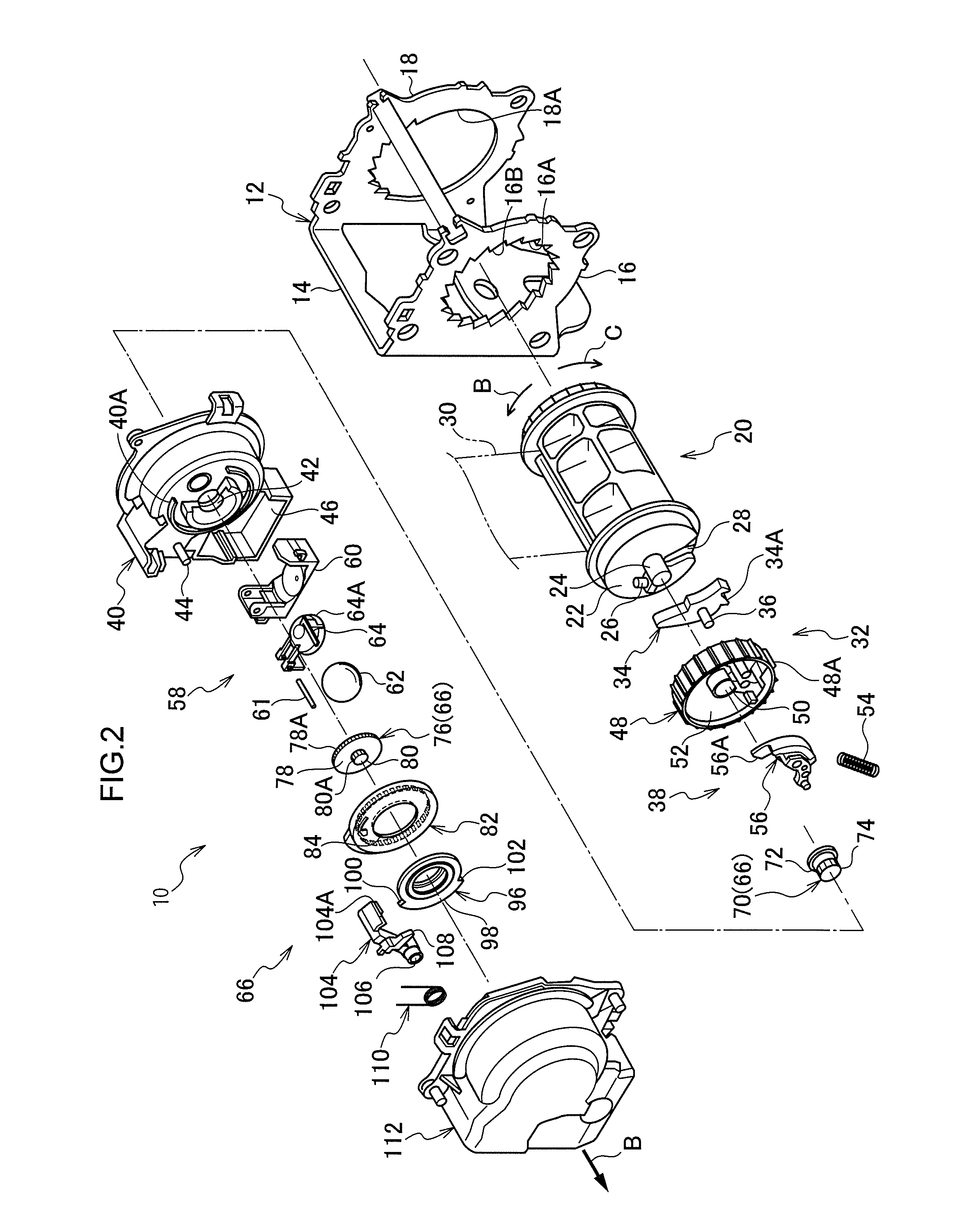
[0040]Hereinafter, an exemplary embodiment of the present invention will be described by referring to the drawings. As illustrated in FIG. 2, a webbing take-up device 10 according to the embodiment of the present invention includes a frame 12, a substantially circular cylinder (columnar) spool 20 which is disposed inside the frame 12, a webbing 30 which extends from the spool 20, a lock mechanism 32 which is disposed at one side in the axial direction (at the side indicated by the arrow A direction of FIG. 2) of the spool 20, and an ALR mechanism 66. Hereinafter, the respective configurations will be described.

[0041]The frame 12 includes a plate-like back plate 14 which is fixed to a vehicle body. Respective leg plates 16 and 18 perpendicularly extend from both ends of the back plate 14 in the width direction, and the frame 12 is substantially formed in a concave shape in a plan view. Respective circular arrangement holes 16A and 18A are formed in the leg plate 16 and the leg plate ...


PUM


Abstract

An extension rib extends from a pressing portion in the take-up direction of an ALR cam and is formed to be able to abut with an ALR pawl. Accordingly, when the ALR cam excessively rotates in the pull-out direction with respect to a set position in a maximal pulled-out state, the ALR pawl abuts the extension rib. Accordingly, it is possible to suppress a state in which the ALR pawl climbs over the pressing portion and engages with a V-gear. Namely, even if a rotation variation of the ALR cam becomes large by setting a speed reduction ratio of speed reduction mechanism to a small value, it is possible to absorb such variation by the extension rib. Thus, it is possible to absorb rotation variation of the ALR cam while improving accuracy of switching timing from the ELR(or ALR) state to the ALR(or ELR) state.

Description

CROSS-REFERENCE TO RELATED APPLICATION [0001]This application claims priority under 35 USC 119 from Japanese Patent Application No. 2012-177393 filed Aug. 9, 2012, the disclosure of which is incorporated by reference herein.BACKGROUND OF THE INVENTION[0002]1. Field of the Invention[0003]The present invention relates to a webbing take-up device having a lock mechanism which prohibits a rotation of a spool in the pull-out direction.[0004]2. Related Art[0005]Among webbing take-up devices, there is known a webbing take-up device in which a so-called ELR (Emergency Locking Retractor) and a so-called ALR (Automatic Locking Retractor) are provided (for example, see Japanese Patent Application Laid-Open (JP-A) No. 10-244905).[0006]In the webbing take-up device disclosed in Japanese Patent Application Laid-Open (JP-A) No. 10-244905, switching is performed between the ALR and the ELR by an ALR mechanism, and the ALR mechanism includes a cam member (a switching cam) that is connected to a take...

Claims


Application Information

Patent Timeline
Patent Type & Authority Applications(United States)
IPC IPC(8): B60P7/08
CPCB60P7/083Y10T24/2117
Inventor YANAGAWA, WATARAYAMADA, KAZUHIRO
Owner KK TOKAI RIKA DENKI SEISAKUSHO
Why Eureka
Try Eureka