Hybrid coupling and assembling method thereof

A coupling and coaxial technology, applied in electric brakes/clutches, permanent magnetic clutches/brakes, asynchronous induction clutches/brakes, etc., can solve problems such as excessive magnetic leakage and difficult assembly of couplings, and achieve reduction Effects of magnetic leakage, simple assembly, and precise speed control

Active Publication Date: 2020-05-29
HEFEI UNIV OF TECH
View PDF5 Cites 7 Cited by
  • Summary
  • Abstract
  • Description
  • Claims
  • Application Information

AI Technical Summary

Problems solved by technology

[0003] In order to solve the technical problems of difficult assembly and more magnetic flux le...

Method used


Image

  • Hybrid coupling and assembling method thereof
  • Hybrid coupling and assembling method thereof
  • Hybrid coupling and assembling method thereof

Examples


Embodiment 1

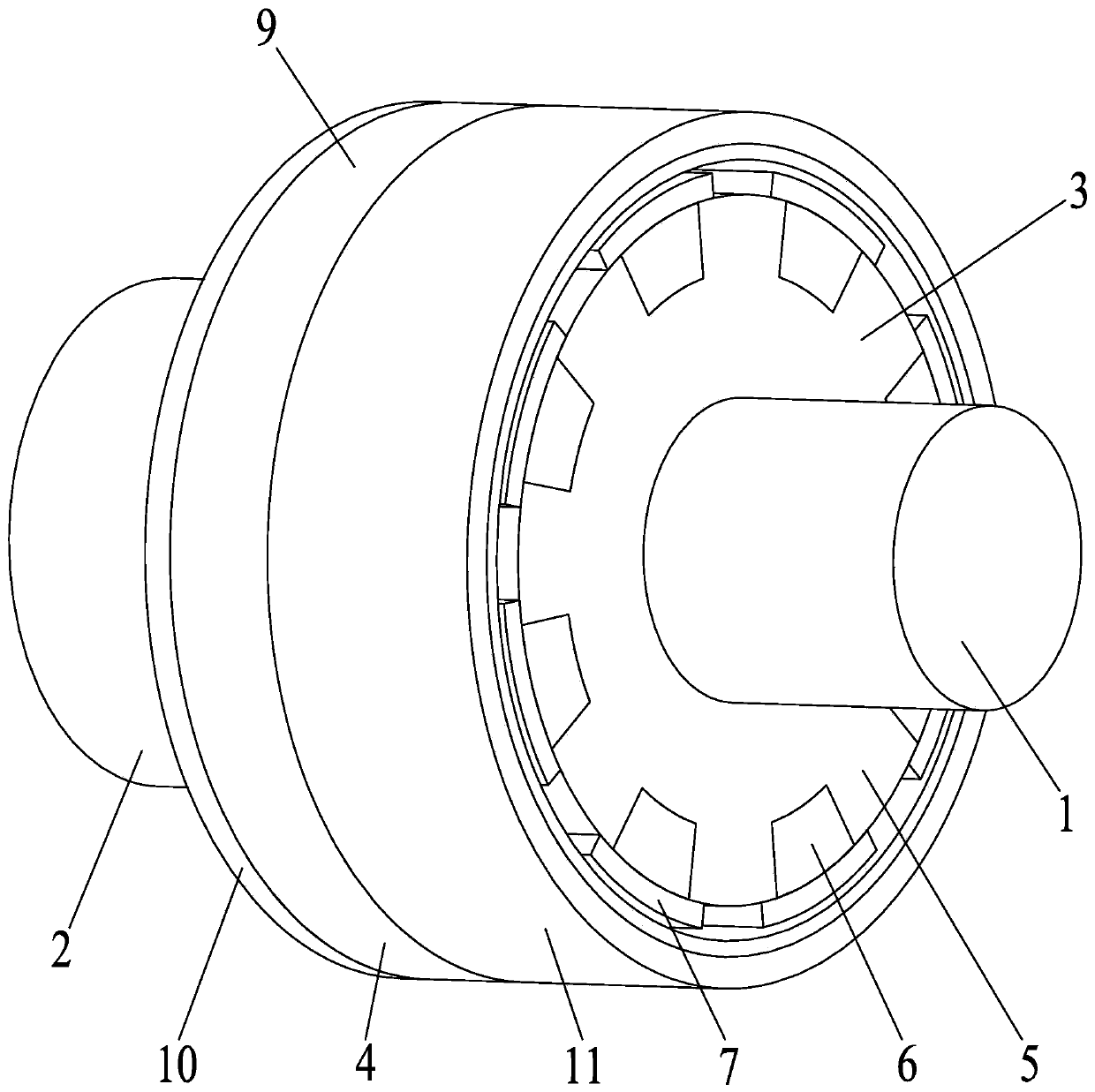
[0049] see figure 1 , this embodiment provides a hybrid coupling for coupling the driving shaft 1 and the driven shaft 2 . Wherein, the hybrid coupling includes a driving disc 3 and a driven disc 4 . In this embodiment, the driving shaft 1 and the driven shaft 2 are not part of the hybrid coupling, but in some other embodiments, the driving shaft 1 and the driven shaft 2 can be used as parts of the hybrid coupling, and can Connect with driving disk 3 and driven disk 4 respectively.

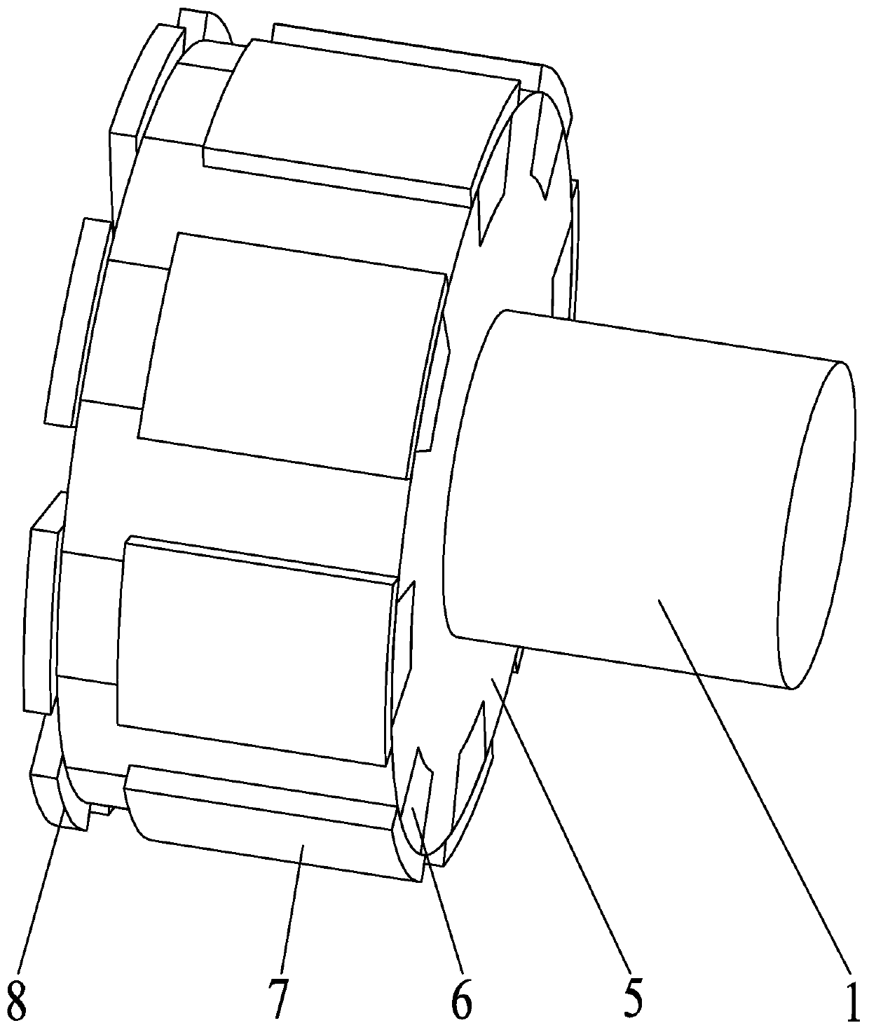
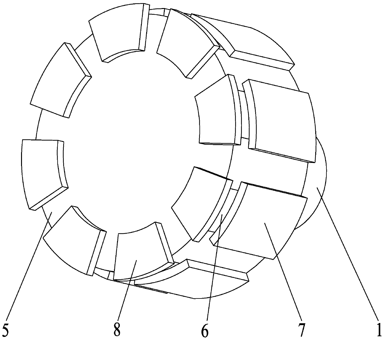
[0050] see figure 2 as well as image 3 , the driving disk 3 is connected to the driving shaft 1 , and in some other embodiments, the driving shaft 1 can be formed directly on the driving disk 3 . The driving disk 3 is used as the connecting structure of the driving shaft 1 , and includes a connecting cylinder 5 , a back iron block 6 , a magnetic coil 1 7 and a magnetic coil 2 8 . The connecting cylinder 5 is arranged coaxially with the driving shaft 1 and is fixedly connected. The driving ...

Embodiment 2

[0069] This embodiment provides a hybrid coupling whose structure is refined on the basis of Embodiment 1. Wherein, the preset distance between each magnetic coil three 12 and the corresponding magnetic coil two 8 is d, and the value range of d is 2-4mm. Of course, what needs to be explained here is that the smaller the value of the distance d, the better, but when the value of the distance d is too low, especially when the value of the distance d is lower than 2mm, the manufacturing of the hybrid coupling at this time The cost will be greatly increased, this is because the second magnetic ring 8 and the corresponding third magnetic ring 12 are attracted together because the distance is too low.

[0070] In some embodiments, the preset distance d between each magnetic coil 3 12 and the corresponding magnetic coil 2 8 is 3 mm, and the distance d can be around 3 mm, and the optimal effect can be achieved at this time.

[0071] In some other embodiments, the distance d between e...

Embodiment 3

[0073] This embodiment provides a hybrid coupling whose structure is refined on the basis of Embodiment 1. Specifically, the total projected area of ​​all magnetic coils-7 on the outer wall of the connecting cylinder 5 accounts for 70%-90% of the area of ​​the cylinder where the projected plane is located. The projection planes of all magnetic coils 2 8 on the end face of the connecting cylinder 5 are located on the same sector 1, and the total projected area accounts for 70%-90% of the area of ​​sector 1; all magnetic coils 3 12 are on the end face of the connecting sleeve 9 The projection planes are located on the same second sector, and the total projected area accounts for 70%-90% of the area of ​​the second sector. What needs to be explained here is that the larger the value of these area ratios in this embodiment, the better the performance of the hybrid coupling. However, when the area ratio is greater than 90%, the gap will be too small, which is not conducive to the ...


PUM


Abstract

The invention discloses a hybrid coupling and an assembling method thereof. The coupling comprises a driving disc and a driven disc. The driving disc comprises a connecting cylinder, back iron blocks,first magnetic rings and second magnetic rings. The driven disc comprises a connecting sleeve, a back iron disc, a back iron sleeve and third magnetic rings. The connecting cylinder is fixedly connected with a driving shaft. The back iron block is embedded into the connecting cylinder. The first magnetic rings are fixed to the connecting cylinder and cover the back iron blocks. The second magnetic rings are fixed to the end face of the connecting cylinder and connected with the back iron blocks. The connecting sleeve is fixedly connected with a driven shaft. An annular groove is formed in theconnecting sleeve. The back iron sleeve sleeves the connecting sleeve and is positioned in the annular groove. The connecting sleeve sleeves the connecting cylinder, so that the driving shaft and thedriven shaft are coaxially arranged. The third magnetic rings are distributed on the side, facing the second magnetic ring, of the back iron disc. The magnetic poles of every two adjacent third magnetic rings are arranged oppositely. The magnetic field intensity of the coupling is improved; the grooves and magnetic leakage amount of the coupling are reduced; collaboration is improved; the assembling difficulty of the coupling is reduced; a torque is increased through vortexes formed through speed changing; and combination is accelerated.

Description

technical field [0001] The invention relates to a shaft coupling in the technical field of shaft coupling, in particular to a hybrid shaft coupling, and also to an assembly method of the shaft coupling. Background technique [0002] Coupling refers to a device that connects two shafts or shafts and rotating parts, and rotates together during the transmission of motion and power, and does not disengage under normal conditions. Couplings are sometimes used as a safety device to prevent excessive loads on the connected parts and play a role in overload protection. The utilization rate of magnetic energy of synchronous permanent magnet coupling is low, and the torque provided is limited. The eddy current permanent magnet coupling cannot achieve synchronous coupling, nor can it achieve more accurate speed control. Moreover, the connection mode of the disc synchronous structure of the coupling and the barrel eddy current structure enables the magnetic energy to strengthen each o...

Claims


Application Information

Patent Timeline
IPC IPC(8): H02K49/04H02K49/10H02K15/00
CPCH02K15/00H02K49/046H02K49/102H02K49/108H02K2213/03
Inventor 陈科史洪扬郑红梅房景仕郭亚军殷磊郑明睿
Owner HEFEI UNIV OF TECH
Why Eureka
Try Eureka