Imaging-material container, ink cartridge, and image forming apparatus

a technology of ink cartridges and containers, applied in printing and other directions, can solve problems such as ejection failure, ink supply shortage in recording heads, and system problems, and achieve the effect of improving the quality of ink supply

Inactive Publication Date: 2013-03-12
RICOH KK
View PDF19 Cites 41 Cited by
  • Summary
  • Abstract
  • Description
  • Claims
  • Application Information

AI Technical Summary

Problems solved by technology

However, this system is not without its problems.
For example, using a flexible thin tube may cause substantial fluid resistance for ink passing through the tube and prevent ink from being supplied on time for ink ejection, resulting in ejection failure.
Further, high-speed recording or ejection of high-viscosity ink may increase the fluid resistance of the tube, causing ink supply shortage in the recording head.
However, when the pressurization method is implemented in a system in which ink is stored in an ink pack made of flexible material to secure the storage stability of ink, the ink pack may not properly deform as the volume of ink in the ink pack decreases, thus preventing the ink from being fully used.
However, this technique requires a complex pump system to be provided in the ink cartridge and a driving unit for driving the pump to be provided in the image forming apparatus, increasing the cost of both the ink cartridge and the image forming apparatus.

Method used


Image

  • Imaging-material container, ink cartridge, and image forming apparatus
  • Imaging-material container, ink cartridge, and image forming apparatus
  • Imaging-material container, ink cartridge, and image forming apparatus

Examples


Embodiment Construction

[0052]In describing embodiments illustrated in the drawings, specific terminology is employed for the sake of clarity. However, the disclosure of this patent specification is not intended to be limited to the specific terminology so selected and it is to be understood that each specific element includes all technical equivalents that operate in a similar manner and achieve similar results.

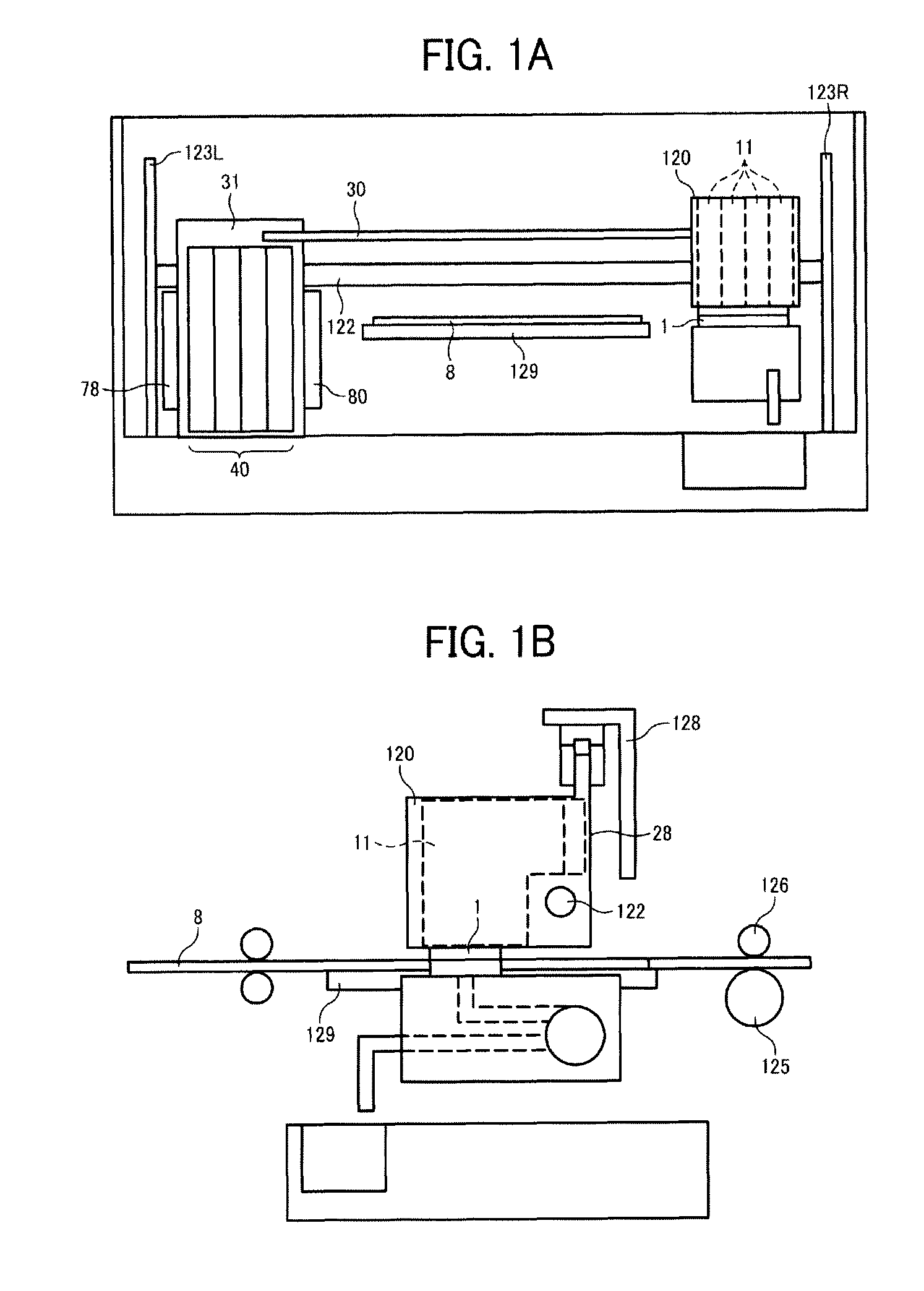
[0053]In this disclosure, the term “image forming apparatus” refers to an apparatus (e.g., droplet ejection apparatus or liquid ejection apparatus) that ejects ink or any other liquid on a medium to form an image on the medium. The medium is made of, for example, paper, string, fiber, cloth, leather, metal, plastic, glass, timber, and ceramic. The term “image formation” used herein includes providing not only meaningful images such as characters and figures but meaningless images such as patterns to the medium. The term “ink” used herein is not limited to “ink” in a narrow sense and includes anythi...


PUM


Abstract

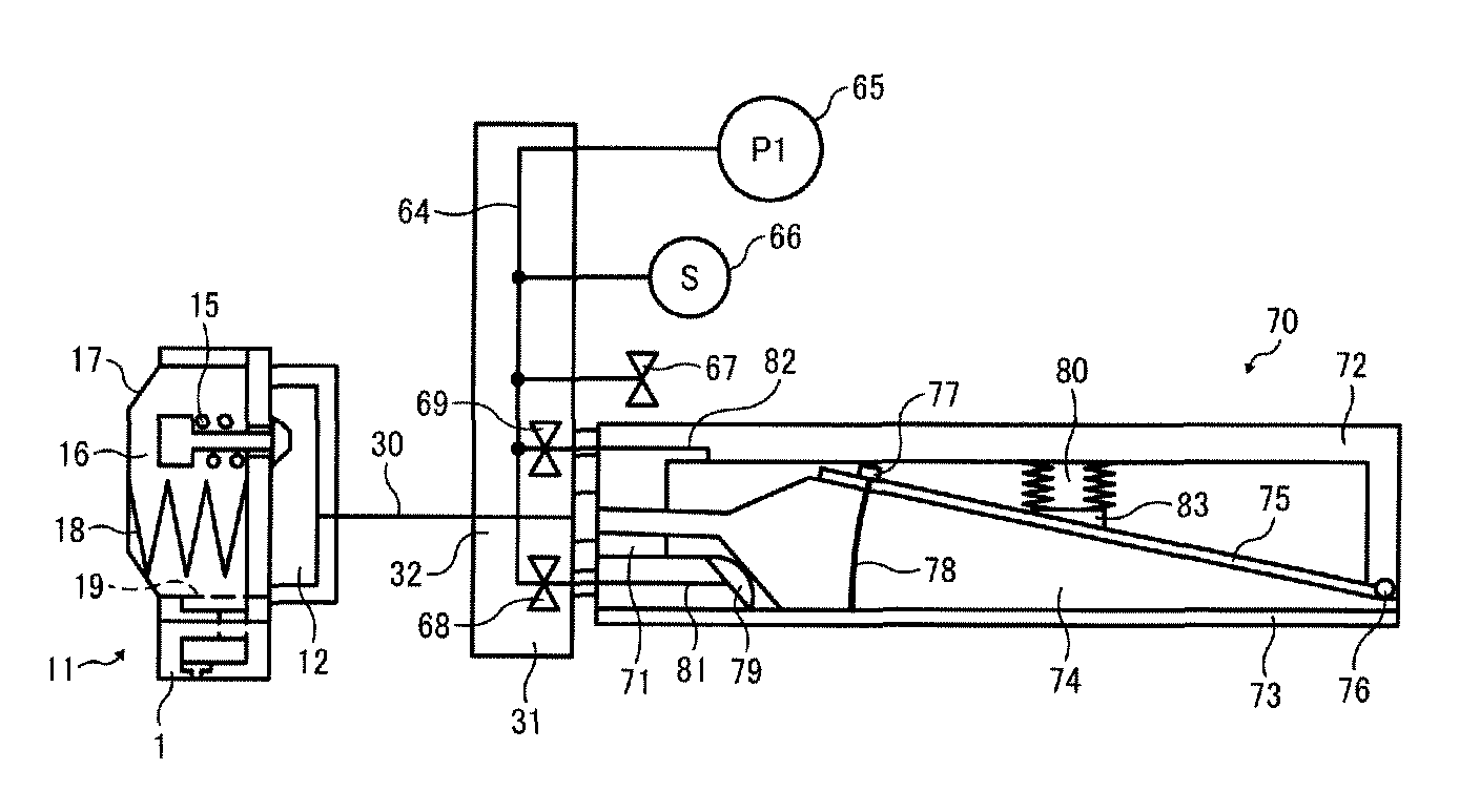
An imaging-material container that stores imaging material to be supplied to an image forming device includes a flexible storage member, a pressure unit, a regulation member, and a pushing unit. The flexible storage member stores imaging material. The pressure unit applies pressure on the flexible storage member. The regulation member contacts the flexible storage member to deform the flexible storage member. The pushing unit moves the regulation member as the imaging material is consumed.

Description

CROSS-REFERENCE TO RELATED APPLICATIONS[0001]The present patent application claims priority pursuant to 35 U.S.C. §119 from Japanese Patent Application No. 2009-122259, filed on May 20, 2009 in the Japan Patent Office, which is incorporated herein by reference in its entirety.BACKGROUND OF THE INVENTION[0002]1. Field of the Invention[0003]Exemplary embodiments of the present disclosure relate to an imaging-material container from which imaging material is supplied to an image forming unit, and more specifically to an imaging-material container capable of reducing the residual amount of imaging material remaining therein after use, an ink cartridge including the imaging-material container, and an image forming apparatus including the ink cartridge.[0004]2. Description of the Background[0005]Image forming apparatuses are used as printers, facsimile machines, copiers, multi-functional peripherals having two or more of the foregoing capabilities, or plotters. As one type of image formin...

Claims


Application Information

Patent Timeline
Patent Type & Authority Patents(United States)
IPC IPC(8): B41J2/175
CPCB41J2/175B41J2/17509B41J2/17513B41J2/1752B41J2/17556B41J2/17596B41J2002/17516
Inventor KATOH, TOMOMIHAYAKAWA, TADASHISOH, IKOHBANNAI, AKIKOTAKEUCHI, SHOTAROKUWATA, MASAHIROTOKUNO, TOSHIROHKUSUNOKI, MASANORI
Owner RICOH KK
Why Eureka
Try Eureka