Apparatus and method for sealing a container

a container and sealing technology, applied in the field of containers sealing apparatus, can solve the problems of container shattering, ceramic materials are not suitable for use, and the use of ceramic cutting tools can be problematic,

Active Publication Date: 2013-04-02
RELCO UK
View PDF25 Cites 5 Cited by
  • Summary
  • Abstract
  • Description
  • Claims
  • Application Information

AI Technical Summary

Benefits of technology

[0008]By concentrating the electrical induction field generally in the region of the cut portion of sealing material and away from the linearly displaceable electrically conductive cutting member, undesirable induction heating of the linearly displaceable electrically conductive cutting member is minimized or prevented. Thermal expansion of the electrically conductive cutting member is thus also minimized or prevented, avoiding potential fouling of the cutting member with the associated component parts of the container sealing apparatus. Because the transfer member is formed from an electrically insulating material, the transfer member is not inductively heated by the induction field.
[0009]The field concentrator thus effectively acts as a shield, preventing the magnetic induction field from heating unwanted electrically conductive component parts of the container sealing apparatus.
[0010]In addition to minimizing or preventing undesirable induction heating of the electrically conductive cutting member, induction heating of other electrically conductive component parts of the container sealing apparatus is also advantageously minimized or prevented by the field concentrator. The efficiency of the induction heating process is thus maximized, enabling rapid induction heating (either directly or indirectly), and thereafter rapid cooling, of the cut portion of sealing material to seal the open top of the container.
[0027]The method may comprise activating the induction coil to inductively heat the cut portion of sealing material, either directly or indirectly, during an initial portion of the predetermined period of time and may thereafter comprise deactivating the induction coil during the remainder of the predetermined period of time. It is during this remainder of the predetermined period of time, following deactivation of the induction coil, that the cut portion of sealing material, and hence the thermosensitive adhesive, rapidly cools. The adhesive typically cures vary rapidly upon cooling, thereby sealing the cut portion of sealing material to the open top of the container.
[0031]In embodiments where the sealing material comprises an electrically insulating sealing material, the method may comprise indirectly inductively heating the cut portion of electrically insulating sealing material. The step of indirectly inductively heating the cut portion of electrically insulating sealing material may comprise inductively heating an electrically conductive transfer surface of the transfer member. Heat generated in the electrically conductive transfer surface by induction heating may then be transferred, typically by conduction, from the electrically conductive transfer surface to the cut portion of electrically insulating sealing material to thereby heat the cut portion of sealing material. Any thermosensitive adhesive carried by the electrically insulating sealing material may thus be softened or melted, thus enabling the cut portion to be adhered to the open top of the container.

Problems solved by technology

Ceramic materials are not, however, suitable for use in situations where the sealing geometry is complex since it becomes economically unfeasible to manufacture a ceramic cutting punch with the required geometry.
The use of a ceramic cutting punch can also be problematic when sealing glass containers since any misalignment between the cutting punch and container could cause the container to shatter when the cutting punch presses the cut portion of sealing material onto the rim of the container.

Method used


Image

  • Apparatus and method for sealing a container
  • Apparatus and method for sealing a container
  • Apparatus and method for sealing a container

Examples


Embodiment Construction

[0038]Embodiments of the present invention will now be described by way of example only and with reference to the accompanying drawings.

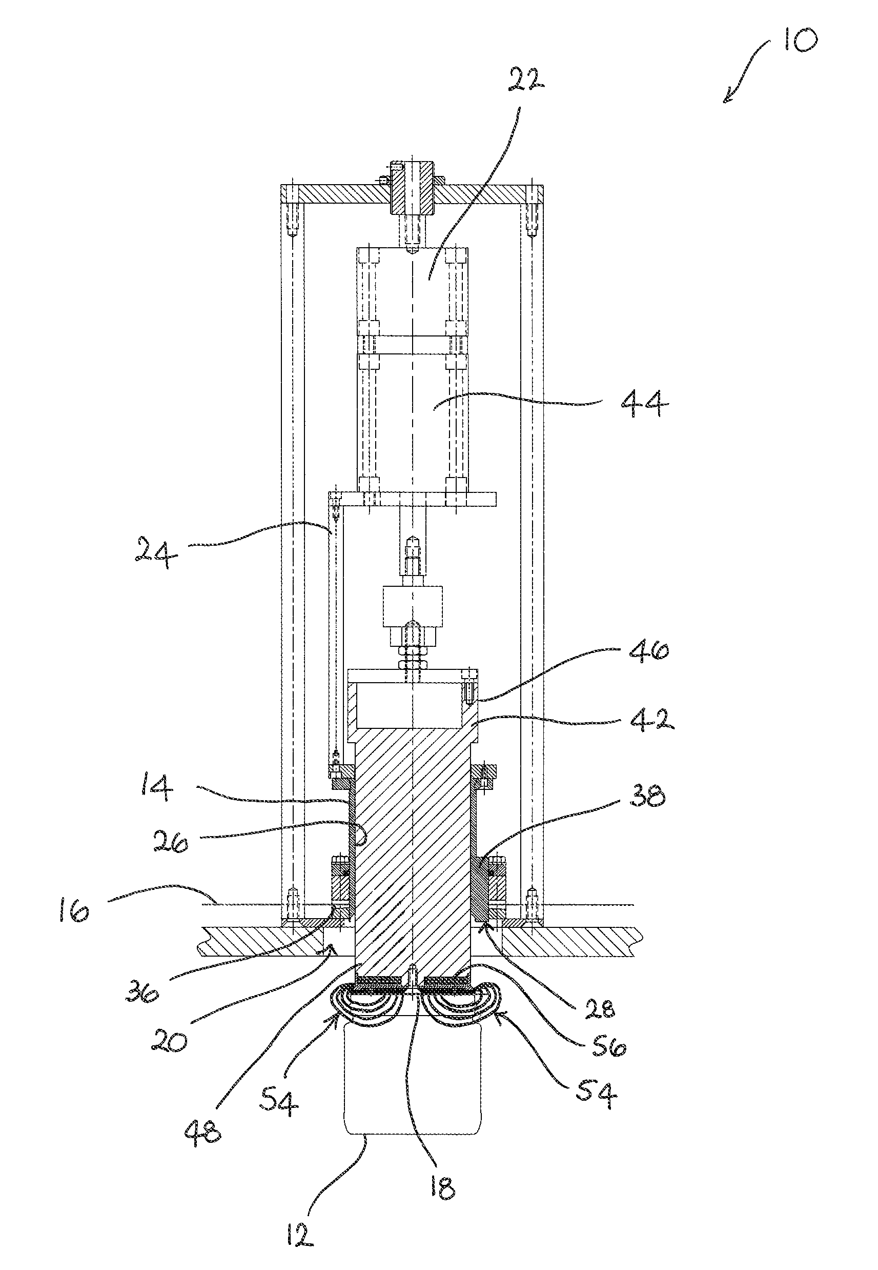
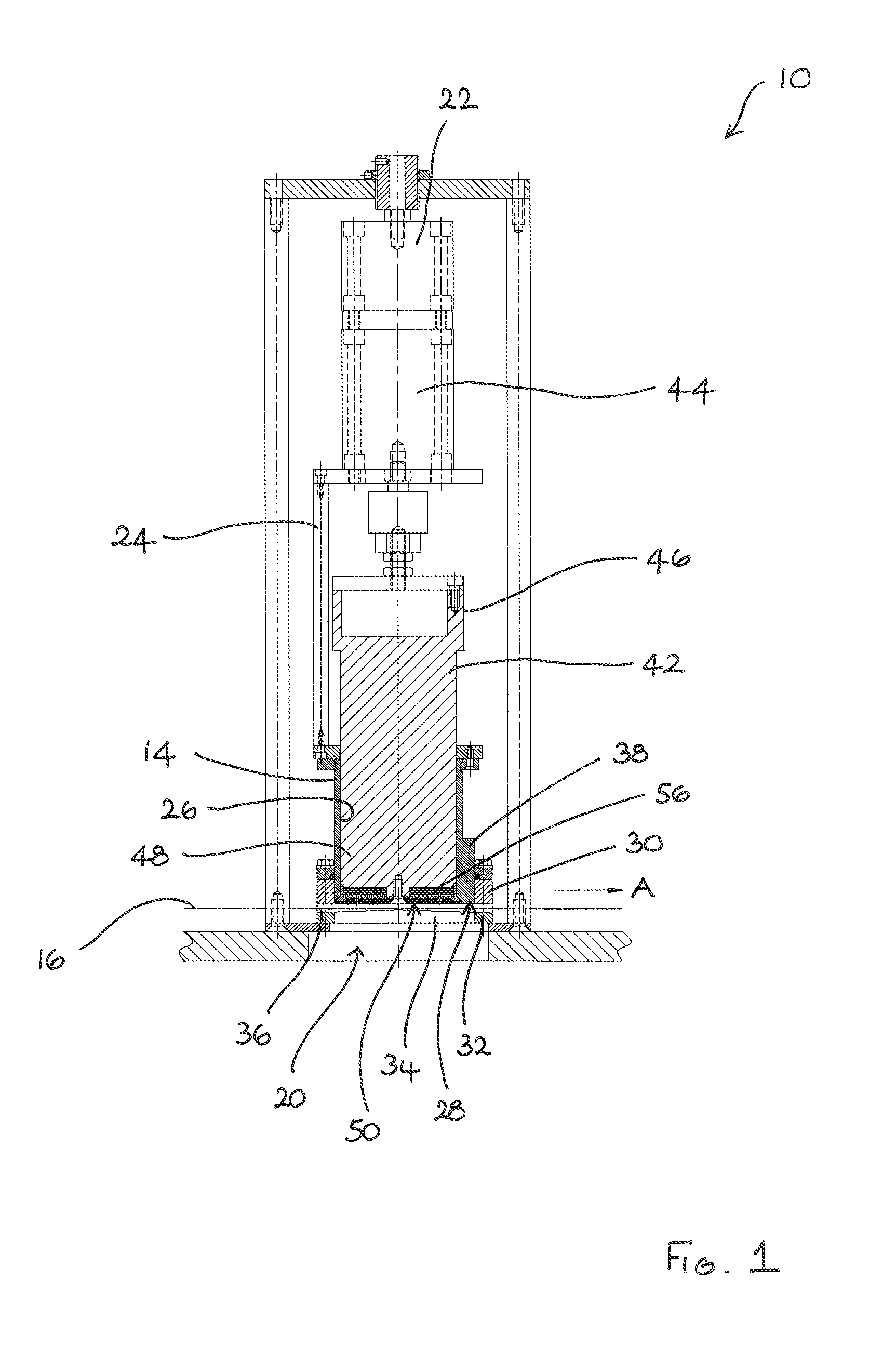
[0039]Referring to the drawings, there is shown a container sealing apparatus 10 for sealing an open top of a container 12 (see FIG. 5). The apparatus 10 can be used to seal containers 12 formed from a variety of materials, such as glass or plastics, having a variety of geometries and intended for a variety of end uses.

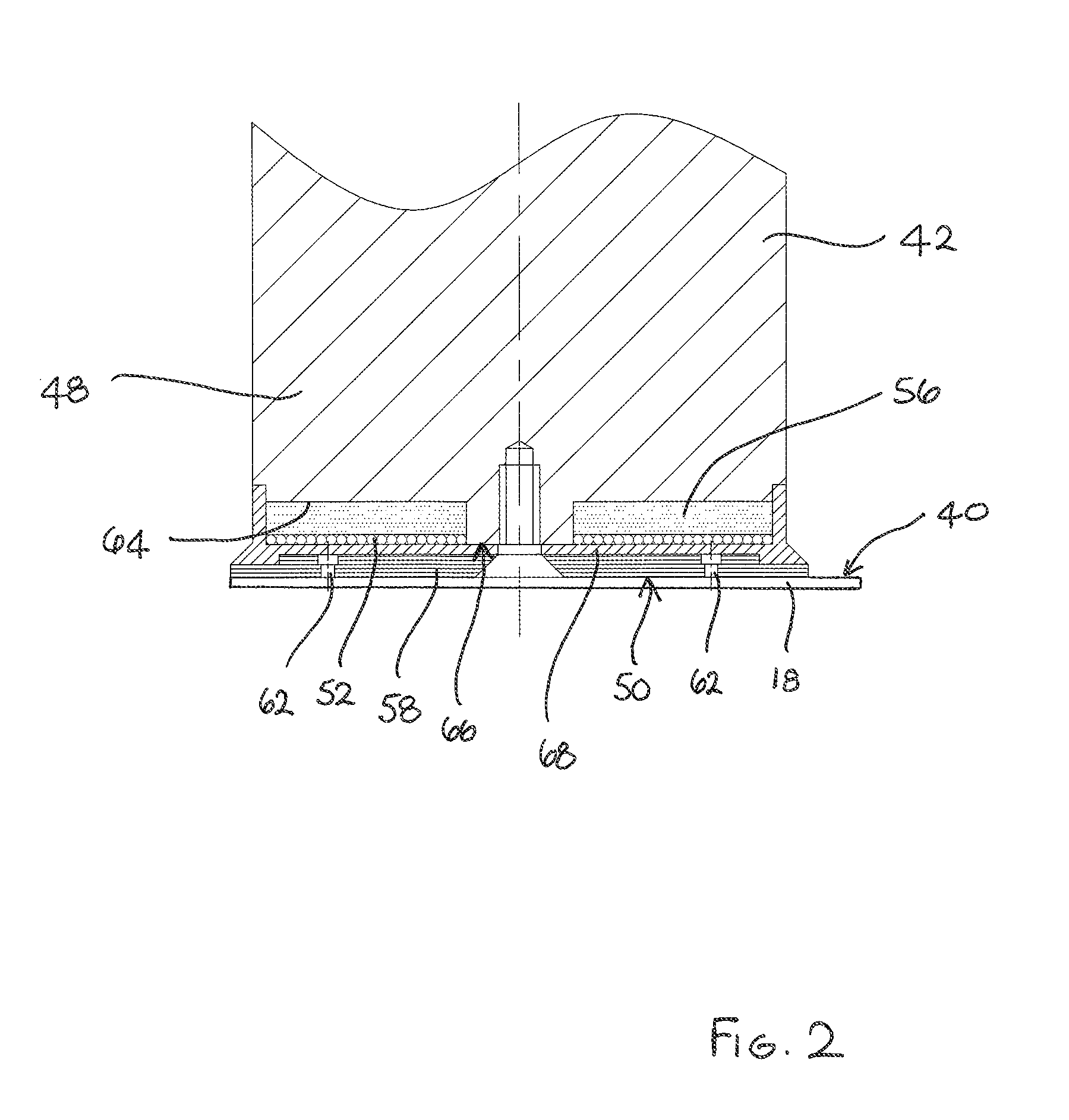
[0040]The apparatus 10 comprises a cutting member 14 which is linearly displaceable between a first position shown in FIG. 1 and a second position shown in FIG. 5. During movement from the first position to the second position, the cutting member 14 cuts a portion of sealing material from a web 16 of sealing material to provide a cut portion 18 of sealing material for sealing to the open top of the container 12. The web 16 of sealing material is typically provided on a supply reel (not shown) and extends through a cutting and sealing ...


PUM

PropertyMeasurementUnit
thicknessaaaaaaaaaa
electrically conductiveaaaaaaaaaa
electrically insulatingaaaaaaaaaa

Abstract

A container sealing apparatus 10 comprises an electrically conductive linearly displaceable cutting member 14 operable to cut a portion 18 of sealing material from a web 16 and an independently linearly displaceable transfer member 42 comprising an electrically insulating material and extendible relative to the cutting member 14 to transfer the cut portion 18 of sealing material to an open top of a container 12 to be sealed. An induction coil 52 produces an induction field 54 for heating the cut portion 18 of sealing material, either directly or indirectly, by induction heating to seal the cut portion 18 of sealing material to the open top of the container 12. The linearly displaceable transfer member 42 holds the cut portion 18 of sealing material against the open top of the container 12 during induction heating. A field concentrator 56 is provided to concentrate the induction field 54 in a desired region away from the linearly displaceable electrically conductive cutting member 14 and other electrically conductive component parts of the apparatus 10 to optimize the induction heating of the cut portion 18 of sealing material.

Description

CROSS-REFERENCE TO RELATED APPLICATION[0001]This application claims priority under 35 USC 119 of United Kingdom Patent Application No. GB 0908238.9, filed May 14, 2009.BACKGROUND OF THE INVENTION[0002]The present invention relates generally to container sealing apparatus and / or to a method for sealing a container. Embodiments of the present invention are concerned particularly with the use of induction heating to apply sealing material to an open top of a container to seal the container.[0003]Induction sealing machines can be used to apply sealing material to the open tops of a variety of containers to seal the containers. In one currently available machine, a ceramic cutting punch is used both to cut a portion of sealing material from a web and to transfer the cut portion of sealing material to the container in a single stroke. The cut portion of sealing material is then inductively heated whilst held against the open top of the container by the cutting member.[0004]The use of cera...

Claims


Application Information

Patent Timeline
Patent Type & Authority Patents(United States)
IPC IPC(8): B65B7/01B65B7/16B65B51/22
CPCB65B7/01B65B7/164B65B51/227B29C65/3656B29C65/48B29C65/7847B29C65/7891B29C66/112B29C66/53461B29C66/72321B29C66/7465B29C66/8122B29C66/81457B29C66/8167B29C66/8242B29C66/8322B29C69/005B29C65/3668B29C66/24221B29K2021/00
Inventor GILL, MARKGILL, PAULADAMS, RICHARD WILLIAMVANKO, DANIELHARMAN, KEITH LESLIE
Owner RELCO UK
Why Eureka
Try Eureka